
In the previous guide (here), we took a look how to configure the timer to generate PWM signal and update the duty cycle in software. In this guide, we shall configure the time with PWM to update the duty cycle using DMA.
In this guide, we shall cover the following:
- Configure timer in DMA mode.
- Configure the DMA.
- Test code.
- Results.
1. Configure timer in DMA mode:
Create new source and header file with name of tim.c and tim.h respectively.
Within tim.h, include the guards:
#ifndef TIM_H_
#define TIM_H_


#endif /* TIM_H_ */
Within the define and endif, include stdint.h as following:
#include "stdint.h"
Declare the following function:
void tim2_pwm(uint16_t *dutyData1, uint16_t *dutyData2, uint16_t len1, uint16_t len2);
The function takes 4 parameters:
- Pointer to duty cycle array for channel1 and channel2.
- Length of each array.
Hence, the header file as following:
#ifndef TIM_H_
#define TIM_H_

#include "stdint.h"


void tim2_pwm(uint16_t *dutyData1, uint16_t *dutyData2, uint16_t  len1, uint16_t len2);


#endif /* TIM_H_ */
Thats all for the header file.
Next in source file, tim.c include tim.h and stm32l0xx.h header file as following:
#include "tim.h"

#include "stm32l0xx.h"
Declare the function as following:
void tim2_pwm(uint16_t *dutyData1, uint16_t *dutyData2, uint16_t len1, uint16_t len2)
within the function:
The following is the same as the previous guide
	/*Enable clock access to GPIOA*/
	RCC->IOPENR |= RCC_IOPENR_GPIOAEN;
	/*Set PA0 and PA1 to alternate function*/
	GPIOA->MODER|=GPIO_MODER_MODE0_1|GPIO_MODER_MODE1_1;
	GPIOA->MODER&=~(GPIO_MODER_MODE0_0|GPIO_MODER_MODE1_0);
	/*Select which alternate function*/
	GPIOA->AFR[0]|=(TIM2_AF<<0)|(TIM2_AF<<4);

	/**Configure timer 2 in PWM mode */

	RCC->APB1ENR|=RCC_APB1ENR_TIM2EN;
	TIM2->PSC=0;
	TIM2->ARR=1600;
	TIM2->CCMR1|=TIM_CCMR1_OC1M_2|TIM_CCMR1_OC1M_1|TIM_CCMR1_OC2M_2|TIM_CCMR1_OC2M_1;
	TIM2->CCER|=TIM_CCER_CC1E|TIM_CCER_CC2E;
Before enabling the timer, we shall enable Capture/compare in DMA mode for both channel1 and channel2.
To enable them, we need to enable Capture/Compare DMA request in TIMx DMA/Interrupt enable register as following:
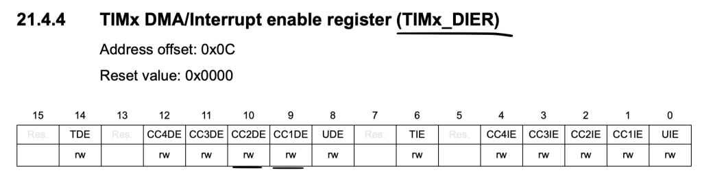
	/*Enable DMA for TIM2*/

	TIM2->DIER|=TIM_DIER_CC1DE|TIM_DIER_CC2DE;
Don’t enable the timer yet.
Thats all for timer configuration.
2. Configure the DMA:
First we need to know which channel is responsible for TIM2_CH1 and TIM2_CH2:
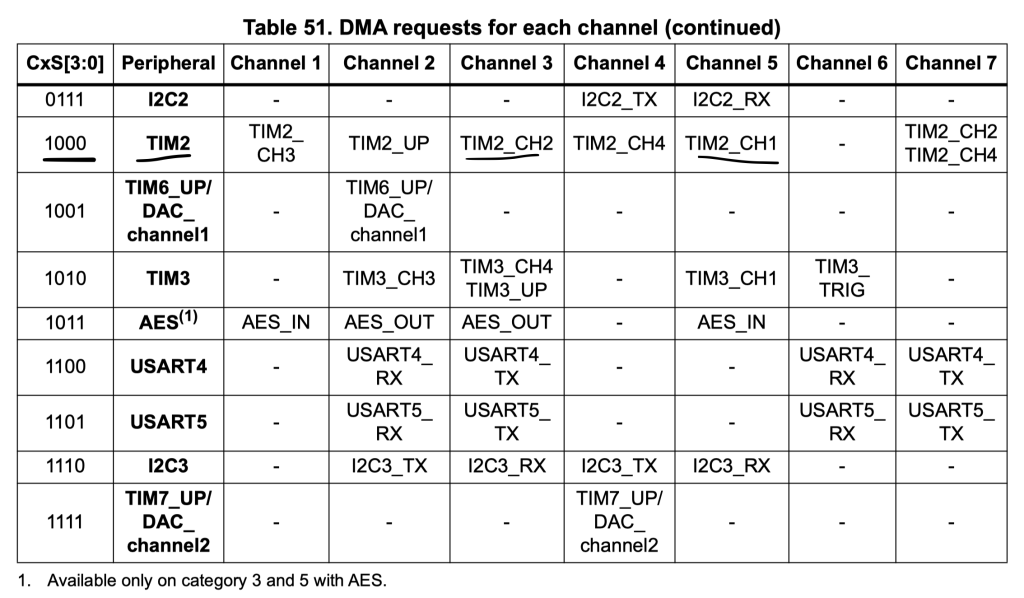
From the table, we can find that Channel5 and Channel3 for TIM2_CH1 and TIM2_CH2 respectively.
First, enable clock access to DMA1:
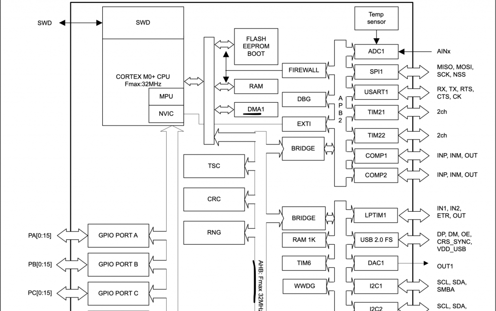
From block diagram, we can find that DMA1 is connected to AHB bus. Hence, we can enable clock access to DMA as following:
RCC->AHBENR|=RCC_AHBENR_DMA1EN;
The DMA_Channel5 and Channel3 shall have the following configuration:
- Memory and peripheral size to be 16-bit.
- Memory increment mode.
- Circular mode.
- Direction, read from memory.
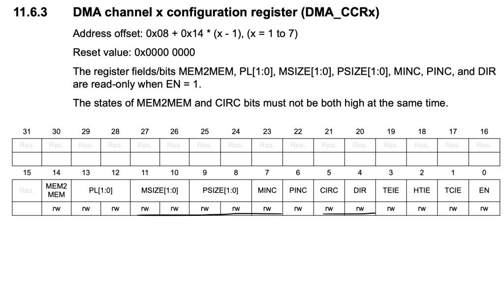
For DMA1_Channel5:
DMA1_Channel5->CCR=DMA_CCR_MSIZE_0|DMA_CCR_PSIZE_0|DMA_CCR_MINC|DMA_CCR_CIRC
			|DMA_CCR_DIR;
For DMA1_Channel3:
	DMA1_Channel3->CCR=DMA_CCR_MSIZE_0|DMA_CCR_PSIZE_0|DMA_CCR_MINC|DMA_CCR_CIRC
			|DMA_CCR_DIR;
Set peripheral address to be TIM2->CCR1 and TIM2->CCR2 respectively:
DMA1_Channel5:
DMA1_Channel5->CPAR=(uint32_t)&TIM2->CCR1;
DMA1_Channel3:
DMA1_Channel3->CPAR=(uint32_t)&TIM2->CCR2;
Set memory destination to be the array passed by the user:
DMA1_Channel5:
DMA1_Channel5->CMAR|=(uint32_t)dutyData1;
DMA1_Channel3:
DMA1_Channel3->CMAR|=(uint32_t)dutyData2;
Set the length for both channel:
DMA1_Channel5:
DMA1_Channel5->CNDTR=len1;
DMA1_Channel3:
DMA1_Channel3->CNDTR=len1;
Set the channel selection to be TIM2:
Since this register doesn’t exist in the main header file, we shall create it as following:
#define DMA_CSELR (*(volatile unsigned int *)(0x400200a8))
DMA1_Channel5
DMA_CSELR|=(0x08<<16);
DMA1_Channel3:
DMA_CSELR|=(0x08<<8);
Enable the DMA channels:
DMA1_Channel5:
DMA1_Channel5->CCR|=DMA_CCR_EN;
DMA1_Channel3:
DMA1_Channel3->CCR|=DMA_CCR_EN;
Finally enable the timer:
TIM2->CR1|=TIM_CR1_CEN;
Hence the source file as following:
#include "tim.h"

#include "stm32l0xx.h"

#define TIM2_AF 0x02

#define DMA_CSELR  (*(volatile unsigned int *)(0x400200a8))

void tim2_pwm(uint16_t *dutyData1, uint16_t *dutyData2, uint16_t  len1, uint16_t len2)
	{


	/*Enable clock access to GPIOA*/
	RCC->IOPENR |= RCC_IOPENR_GPIOAEN;
	/*Set PA0 and PA1 to alternate function*/
	GPIOA->MODER|=GPIO_MODER_MODE0_1|GPIO_MODER_MODE1_1;
	GPIOA->MODER&=~(GPIO_MODER_MODE0_0|GPIO_MODER_MODE1_0);
	/*Select which alternate function*/
	GPIOA->AFR[0]|=(TIM2_AF<<0)|(TIM2_AF<<4);

	/**Configure timer 2 in PWM mode */

	RCC->APB1ENR|=RCC_APB1ENR_TIM2EN;
	TIM2->PSC=0;
	TIM2->ARR=1600;
	TIM2->CCMR1|=TIM_CCMR1_OC1M_2|TIM_CCMR1_OC1M_1|TIM_CCMR1_OC2M_2|TIM_CCMR1_OC2M_1;
	TIM2->CCER|=TIM_CCER_CC1E|TIM_CCER_CC2E;

	/*Enable DMA for TIM2*/

	TIM2->DIER|=TIM_DIER_CC1DE|TIM_DIER_CC2DE;

	/*DMA Setup*/

	RCC->AHBENR|=RCC_AHBENR_DMA1EN;

	/*DMA1_CH5 is for TIM2_CH1
	 * DMA1_CH3 is for TIM2_CH3
	 * */


	DMA1_Channel5->CCR=DMA_CCR_MSIZE_0|DMA_CCR_PSIZE_0|DMA_CCR_MINC|DMA_CCR_CIRC
			|DMA_CCR_DIR;

	DMA1_Channel5->CPAR=(uint32_t)&TIM2->CCR1;

	DMA1_Channel5->CMAR|=(uint32_t)dutyData1;

	DMA1_Channel5->CNDTR=len1;

	DMA_CSELR|=(0x08<<16);

	DMA1_Channel5->CCR|=DMA_CCR_EN;


	DMA1_Channel3->CCR=DMA_CCR_MSIZE_0|DMA_CCR_PSIZE_0|DMA_CCR_MINC|DMA_CCR_CIRC
			|DMA_CCR_DIR;

	DMA1_Channel3->CPAR=(uint32_t)&TIM2->CCR2;

	DMA1_Channel3->CMAR|=(uint32_t)dutyData2;

	DMA1_Channel3->CNDTR=len1;

	DMA_CSELR|=(0x08<<8);

	DMA1_Channel3->CCR|=DMA_CCR_EN;


	TIM2->CR1|=TIM_CR1_CEN;

	}
3. Test code:
Within main.c :
#include "tim.h"

uint16_t lookUp1[] = {0,50 ,100 ,151 ,201 ,250 ,300 ,349 ,398 ,446 ,494 ,542 ,589 ,635 ,681
	,726 ,771 ,814 ,857 ,899 ,940 ,981 ,1020 ,1058 ,1095 ,1131 ,1166 ,1200 ,1233 ,1264
	,1294 ,1323 ,1351 ,1377 ,1402 ,1426 ,1448 ,1468 ,1488 ,1505 ,1522 ,1536 ,1550 ,1561
	,1572 ,1580 ,1587 ,1593 ,1597 ,1599 ,1600 ,1599 ,1597 ,1593 ,1587 ,1580 ,1572 ,1561
	,1550 ,1536 ,1522 ,1505 ,1488 ,1468 ,1448 ,1426 ,1402 ,1377 ,1351 ,1323 ,1294 ,1264
	,1233 ,1200 ,1166 ,1131 ,1095 ,1058 ,1020 ,981 ,940 ,899 ,857 ,814 ,771 ,726 ,681 ,635
	,589 ,542 ,494 ,446 ,398 ,349 ,300 ,250 ,201 ,151 ,100 ,50,0 ,0 ,0 ,0 ,0 ,0 ,0 ,0 ,0 ,0
	,0 ,0 ,0 ,0 ,0 ,0 ,0 ,0 ,0 ,0 ,0 ,0 ,0 ,0 ,0 ,0 ,0 ,0 ,0 ,0 ,0 ,0 ,0 ,0 ,0 ,0 ,0 ,0 ,0 ,0
	,0 ,0 ,0 ,0 ,0 ,0 ,0 ,0 ,0 ,0 ,0 ,0 ,0 ,0 ,0 ,0 ,0 ,0 ,0 ,0 ,0 ,0 ,0 ,0 ,0 ,0 ,0 ,0 ,0 ,0
	,0 ,0 ,0 ,0 ,0 ,0 ,0 ,0 ,0 ,0 ,0 ,0 ,0 ,0 ,0 ,0 ,0 ,0 ,0 ,0 ,0 ,0 ,0 ,0 ,0 ,0 ,0 ,0 ,0 ,0 ,0};

uint16_t lookUp2[] = {0 ,0 ,0 ,0 ,0 ,0 ,0 ,0 ,0 ,0 ,0 ,0 ,0 ,0 ,0 ,0 ,0 ,0 ,0 ,0 ,0 ,0 ,0 ,0 ,0
	,0 ,0 ,0 ,0 ,0 ,0 ,0 ,0 ,0 ,0 ,0 ,0 ,0 ,0 ,0 ,0 ,0 ,0 ,0 ,0 ,0 ,0 ,0 ,0 ,0 ,0 ,0 ,0 ,0 ,0
	,0 ,0 ,0 ,0 ,0 ,0 ,0 ,0 ,0 ,0 ,0 ,0 ,0 ,0 ,0 ,0 ,0 ,0 ,0 ,0 ,0 ,0 ,0 ,0 ,0 ,0 ,0 ,0 ,0 ,0
	,0 ,0 ,0 ,0 ,0 ,0 ,0 ,0 ,0 ,0 ,0 ,0 ,0 ,0 ,0 ,50 ,100 ,151 ,201 ,250 ,300 ,349 ,398 ,446 ,494
	,542 ,589 ,635 ,681 ,726 ,771 ,814 ,857 ,899 ,940 ,981 ,1020 ,1058 ,1095 ,1131 ,1166 ,1200 ,1233
	,1264 ,1294 ,1323 ,1351 ,1377 ,1402 ,1426 ,1448 ,1468 ,1488 ,1505 ,1522 ,1536 ,1550 ,1561 ,1572 ,1580
	,1587 ,1593 ,1597 ,1599 ,1600 ,1599 ,1597 ,1593 ,1587 ,1580 ,1572 ,1561 ,1550 ,1536 ,1522 ,1505 ,1488
	,1468 ,1448 ,1426 ,1402 ,1377 ,1351 ,1323 ,1294 ,1264 ,1233 ,1200 ,1166 ,1131 ,1095 ,1058 ,1020 ,981
	,940 ,899 ,857 ,814 ,771 ,726 ,681 ,635 ,589 ,542 ,494 ,446 ,398 ,349 ,300 ,250 ,201 ,151 ,100 ,50 ,0,0};


int main(void)
{
	tim2_pwm(lookUp1,lookUp2, 200,200 );

	while(1)
	{


	}

}
4. Results:
By probing PA0 and PA1 using oscilloscope, you should get the following results:

Happy coding 🙂
Add Comment