
In the previous guide (here), we tool a look for SPI in duplex mode using polling mode. In this guide, we shall see how to do SPI Full duplex using DMA.
In this guide, we shall cover the following:
- Enable RXDMA for SPI.
- Configure DMA.
- SPI RX with DMA
- MPU9250 connection with STM32 and code modifucation.
- Code.
- Results.
1. Enable RXDMA for SPI:
Before enabling the RXDMA for SPI. we need to add this enum to spi.h header file as following:
typedef enum
{
	Rx_Done=1,
	RX_Inprogress=0

}SPI_RXStatus;
Also, add these two functions:
void spi1_rx_dma(uint8_t * data, uint16_t len);
uint8_t rx_status();
Within source file spi.c, add the following volatile variable:
volatile uint8_t rx_done;
We start off by SPI TX DMA guide from here.
To enable RX in DMA for SPI, simply enable RXDMA from SPI1_CR2 register as following:
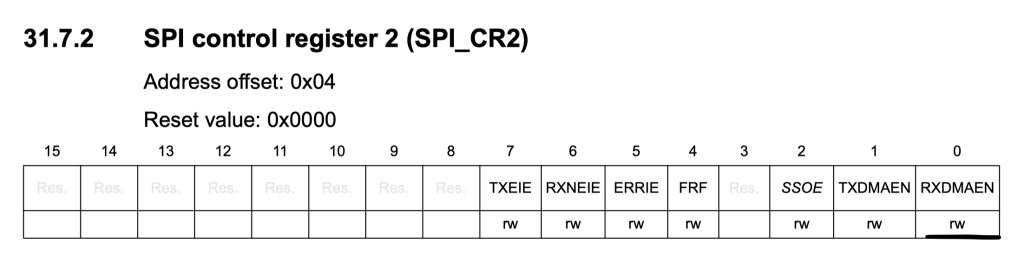
	/*Enable DMARX*/
	SPI1->CR2|=SPI_CR2_RXDMAEN;
The reset similar for SPI TX in DMA.
2. Configure DMA:
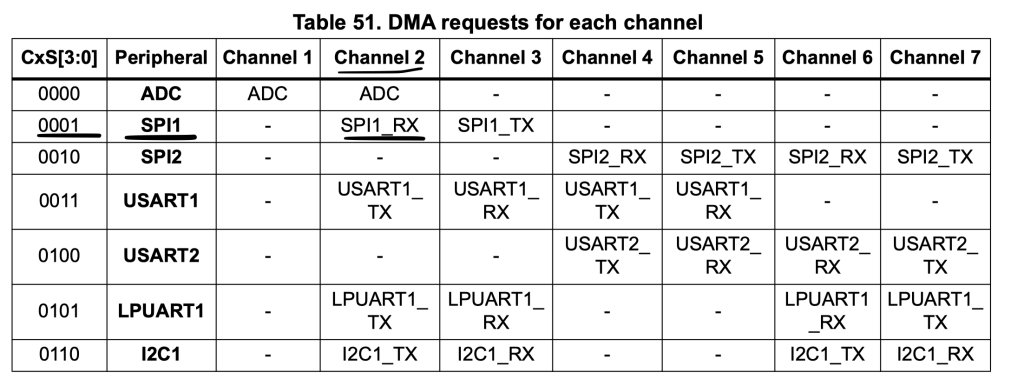
Before configuring DMA for SPI RX, we need to find which channel responsible for SPI_RX.
From DMA requests for each channel, we can find that SPI_RX is Channel2:
Hence, we shall configure the channel with the following parameter:
- Memory increment mode.
- Transfer complete interrupt enable.
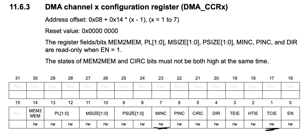
	/*DMA1 Channel 2 for SPI_RX*/


	DMA1_Channel2->CCR|=DMA_CCR_MINC|DMA_CCR_TCIE;
The interrupt is already enabled in NVIC from the TX part since they both share same interrupt handler
Set the peripheral address to be SPI1->DR as following:
	/*Set the peripheral address*/
	DMA1_Channel2->CPAR =(uint32_t)&SPI1->DR;
Set the channel to be 1 for SPI1 as following:
	/*Set the channel selection*/
	DMA_CSELR|=(0x01<<4);
For the interrupt handler, add the following if statement to the interrupt handler:
if(DMA1->ISR & DMA_ISR_TCIF2)
	{
		/*Set tx_done to 1*/
		rx_done=1;

		/*Clear Interrupt flag*/
		DMA1->IFCR =DMA_IFCR_CTCIF2;

		/*Disable the stream*/
		DMA1_Channel2->CCR&=~DMA_CCR_EN;

	}
That all for DMA configuration.
3. SPI RX in DMA:
To receive data from SPI bus, declare the following function:
void spi1_rx_dma(uint8_t * data, uint16_t len)
The function takes two arguments:
- Pointer to data to be read.
- Length of the data to be received.
Within the function:
Reset the rx_done flag:
	/*Reset rx flag*/
	rx_done=0;
Set the memory address to be the pointer passed by the user:
	/*Set the memory address to be data*/
	DMA1_Channel2->CMAR=(uint32_t)&data[0];
Set the length to the length passed by the user:
	/*Set the length*/
	DMA1_Channel2->CNDTR=len;
Clear the flag:
	/*Clear Interrupt flag*/
	DMA1->IFCR =DMA_IFCR_CTCIF2;
	/*Launch the DMA transfer*/
	DMA1_Channel2->CCR|=DMA_CCR_EN;
Thats all for SPI_RX_DMA.
To check if the received stream is finished:
uint8_t rx_status()
{
	if(rx_done==0){return RX_Inprogress;}
	else {return Rx_Done;}
}
Thats all for the SPI in DMA mode.
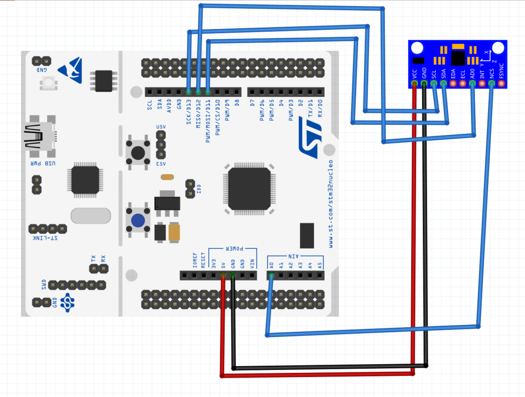
4.MPU9250 connection with STM32 and code modification:
The connection as following:
uint8_t MPU9250_accelUpdate(void)
{
	uint8_t data[6]={0x3B|READ_FLAG,0xFF,0xFF,0xFF,0xFF,0xFF};
	cs_low();
	spi1_rx_dma(accelBuf, 6);
	spi1_tx_dma(&data, 6);
	while(rx_status()==RX_Inprogress);
	cs_high();
	return 0;

}
Declare a buffer which will hold 6 bytes where first byte is the address to be read with read flag and 5 bytes of dummy data to keep the clock generated.
Set the cs pin to low.
start SPI_RX_DMA.
transfer the address to be send with dummy data.
wait until rx finished transfer.
Set CS to high.
Same thing goes to gyroscope:
uint8_t MPU9250_gyroUpdate(void)
{
	uint8_t data[6]={0x43|READ_FLAG,0xFF,0xFF,0xFF,0xFF,0xFF};
	cs_low();
	spi1_rx_dma(gyroBuf,6);
	spi1_tx_dma(&data, 6);
	while(rx_status()==RX_Inprogress);
	cs_high();
	return 0;
}
main.c:
#include "spi.h"
#include "MPU9250.h"
#include "delay.h"
#include "stdio.h"
#include "uart.h"
int main(void)
{
uart_init();
systick_init_ms(2097000);
spi_dma_init();
MPU9250_beginAccel(ACC_FULL_SCALE_16_G);
MPU9250_beginGyro(GYRO_FULL_SCALE_2000_DPS);
printf("hello from STM32L053\r\n");
while(1)
{
MPU9250_accelUpdate();
MPU9250_gyroUpdate();
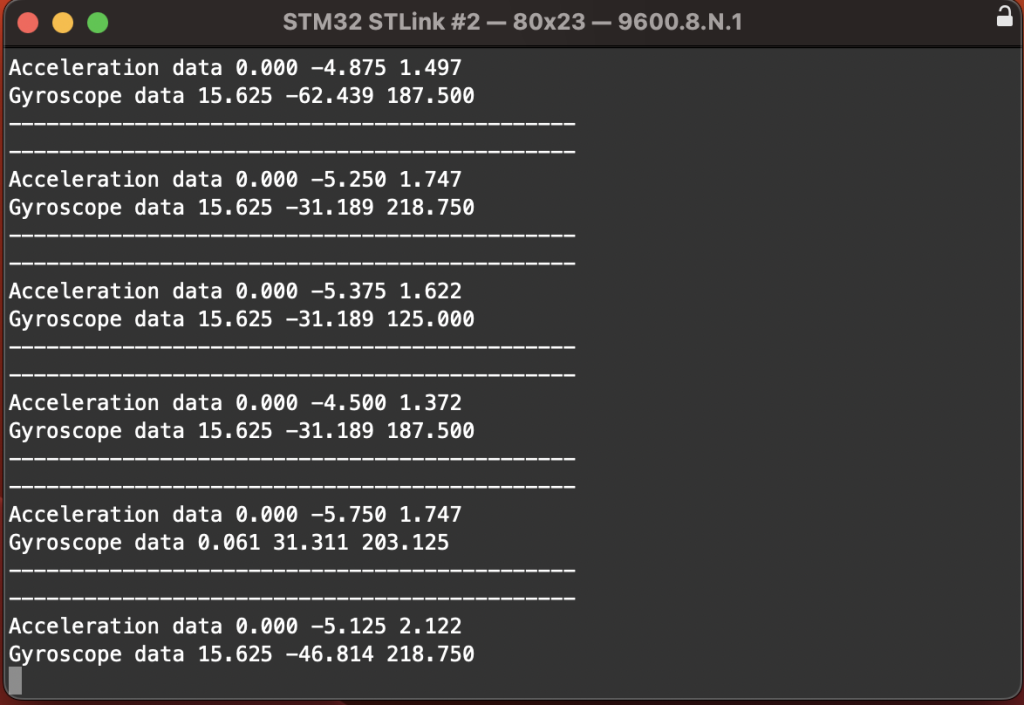
printf("---------------------------------------------\r\n");
printf("Acceleration data %0.3f %0.3f %0.3f \r\n",MPU9250_accelX(),MPU9250_accelY(),MPU9250_accelZ());
printf("Gyroscope data %0.3f %0.3f %0.3f \r\n",MPU9250_gyroX(),MPU9250_gyroY(),MPU9250_gyroZ());
printf("---------------------------------------------\r\n");
delay(500);
}
}
5. Code:
You may download the code from here:
6. Results:
Add Comment