In the previous guide (here), we took a look at keypad structure and how to initialize the keypad pins. In this guide, we shall develop the algorithm to read from keypad.
In this guide, we shall cover the following:
- Read keypad function.
- Code.
- Results.
6. Read keypad function:
Before developing the keypad_read function, we need first to declare the keypad structure as following:
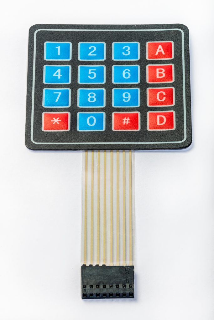
Since the keypad is 4×4 with same layout in this picture:
Hence, the keypad layout as following:
const unsigned char keymap[4][4]=
	{
		{'1', '2', '3', 'A' },
		{'4', '5', '6', 'B' },
		{'7', '8', '9', 'C' },
		{'*', '0', '#', 'D' }


	};
This will hold the keypad map as two dimensional array.
Next, we need to scan the entire keypad. to do so, we can use simple for loop to do this.
Before dealing with for loop, we shall declare the following array which will hold the state of pins to be write to GPIOC port as following:
const uint32_t clo_state[4]={	(GPIO_BSRR_BR4|GPIO_BSRR_BS5|GPIO_BSRR_BS6|GPIO_BSRR_BS7),
						(GPIO_BSRR_BS4|GPIO_BSRR_BR5|GPIO_BSRR_BS6|GPIO_BSRR_BS7),
						(GPIO_BSRR_BS4|GPIO_BSRR_BS5|GPIO_BSRR_BR6|GPIO_BSRR_BS7),
						(GPIO_BSRR_BS4|GPIO_BSRR_BS5|GPIO_BSRR_BS6|GPIO_BSRR_BR7)
};
Since the row pins are set to input with pullup resistors, we need to set the desired column to low in order to have the ability to read the pin. Since using pullup requires the push button to be connected to ground as following:
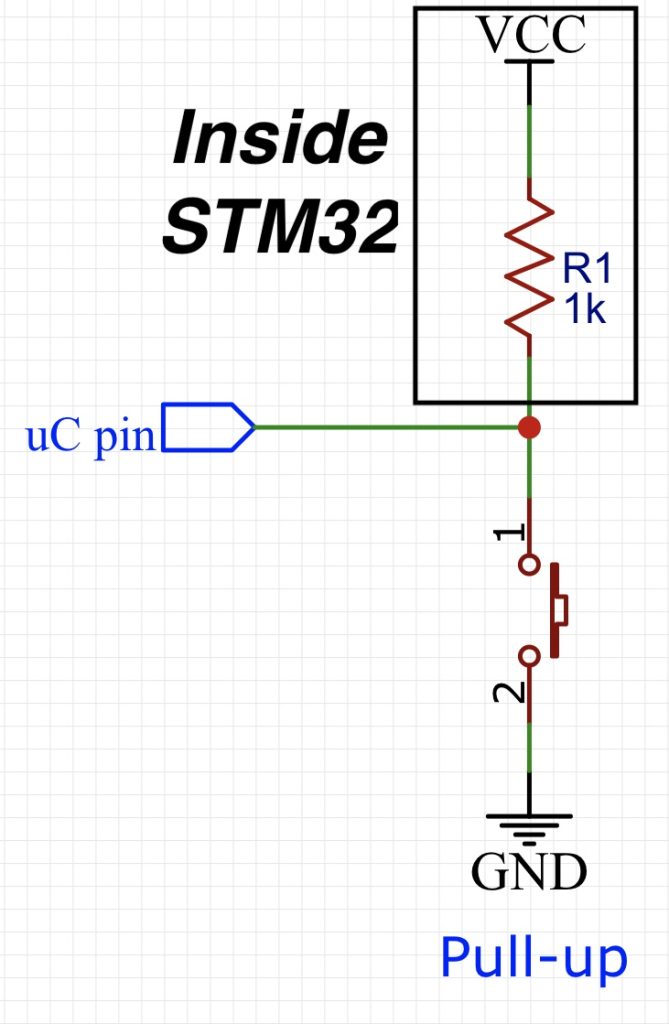
Hence, we need to set the column bit to zero or ground.
Now, we shall develop the keypad_read function:
Within the following function:
char keypad_read(void)
{
Declare the following two variables:
unsigned char key=0,data=0;
First variable to hold the key value and second one to hold the data read from the row pins.
Now, declare for loop as following:
for (int i=0;i<4;i++)
	{
within for loop, set the column state from the array as following:
GPIOC->BSRR=clo_state[i];
Now read the first for bit of the IDR register as following:
data=(GPIOC->IDR)&0xF; /*Get rid of data from bit 5 to bit31*/
The reason behind anding the read value with 0xF to get rid of values from bit 4 to 31 which they are not needed.
When no key is pressed, the data will be 0xF due to pullup resistors. When a key is pressed, a value other than 0xF will be read, hence, when the value is not 0xF, we shall decode the required value as following:
if(data != 0xF)
		{
			key=decode_keypad(i,data);
		}
Then close the for loop and return the key value as following:
}

	return key;
For decoding keypad function:
static char decode_keypad(uint8_t col, uint8_t row)
It takes two arguments as following:
- col value with is the current column indicated by variable i.
- row value which is indicated by the read data.
Within the function:
	if (row == 0xE) return keymap[0][col];
	if (row == 0xD) return keymap[1][col];
	if (row == 0xB) return keymap[2][col];
	if (row == 0x7) return keymap[3][col];
	return 0;
The function will check the row value with 0xE, 0xD, 0xB and 0x7 respectively to determine which key in the column is pressed and return the respective value.
Hence, the entire source code as following:
#include "stm32f4xx.h"

#include "keypad.h"

static char decode_keypad(uint8_t col, uint8_t row);


const unsigned char keymap[4][4]=
	{
		{'1', '2', '3', 'A' },
		{'4', '5', '6', 'B' },
		{'7', '8', '9', 'C' },
		{'*', '0', '#', 'D' }


	};


const uint32_t clo_state[4]={	(GPIO_BSRR_BR4|GPIO_BSRR_BS5|GPIO_BSRR_BS6|GPIO_BSRR_BS7),
						(GPIO_BSRR_BS4|GPIO_BSRR_BR5|GPIO_BSRR_BS6|GPIO_BSRR_BS7),
						(GPIO_BSRR_BS4|GPIO_BSRR_BS5|GPIO_BSRR_BR6|GPIO_BSRR_BS7),
						(GPIO_BSRR_BS4|GPIO_BSRR_BS5|GPIO_BSRR_BS6|GPIO_BSRR_BR7)
};


void keypad_init(void)
{

	/*Enable clock access to GPIOC*/
	RCC->AHB1ENR|=RCC_AHB1ENR_GPIOCEN;

	/*Set PC0 to PC3 as input*/
	GPIOC->MODER &= ~(GPIO_MODER_MODE0|GPIO_MODER_MODE1|GPIO_MODER_MODE2|GPIO_MODER_MODE3);

	/* Activate internal pullup resistor for PC0 to PC3*/
	GPIOC->PUPDR|=GPIO_PUPDR_PUPD0_0|GPIO_PUPDR_PUPD1_0|GPIO_PUPDR_PUPD2_0|GPIO_PUPDR_PUPD3_0;

	/*Set PC4 to PC7 as output*/
	GPIOC->MODER |= GPIO_MODER_MODE4_0|GPIO_MODER_MODE5_0|GPIO_MODER_MODE6_0|GPIO_MODER_MODE7_0;

	GPIOC->MODER &=~( GPIO_MODER_MODE4_1|GPIO_MODER_MODE5_1|GPIO_MODER_MODE6_1|GPIO_MODER_MODE7_1);

	/*Set PC4 to PC7 as high*/

	GPIOC->BSRR = GPIO_BSRR_BS4|GPIO_BSRR_BS5|GPIO_BSRR_BS6|GPIO_BSRR_BS7;
}


char keypad_read(void)
{

	unsigned char key=0,data=0;

	for (int i=0;i<4;i++)
	{

		GPIOC->BSRR=clo_state[i];

		data=(GPIOC->IDR)&0xF; /*Get rid of data from bit 5 to bit31*/

		if(data != 0xF)
		{
			key=decode_keypad(i,data);
		}

	}

	return key;
}


static char decode_keypad(uint8_t col, uint8_t row)
{

	if (row == 0xE) return keymap[0][col];
	if (row == 0xD) return keymap[1][col];
	if (row == 0xB) return keymap[2][col];
	if (row == 0x7) return keymap[3][col];
	return 0;
}
In main.c :
#include "delay.h"
#include "stdio.h"
#include "LiquidCrystal_PCF8574.h"
#include "keypad.h"


char lcd_data[30];

char key;


int main(void)
{


	lcd_init();
	keypad_init();


	while(1)
	{
		key=keypad_read();
		if(key)
		{
			setCursor(0, 0);
			sprintf(lcd_data,"Key pressed is %c",key);
			lcd_send_string(lcd_data);
		}
		delay(30);

	}

}
7. Code:
You may download from here:
8. Results:
Happy coding 🙂
Add Comment