In this two part guide, we shall see how to interface 4×4 Keypad with STM32F411RE-Nucleo and develop the algorithm required to read the keypad.
In this guide, we shall cover the following:
- Key structure.
- Reading keypad.
- Keypad pinout
- Connection.
- Initializing the required pins.
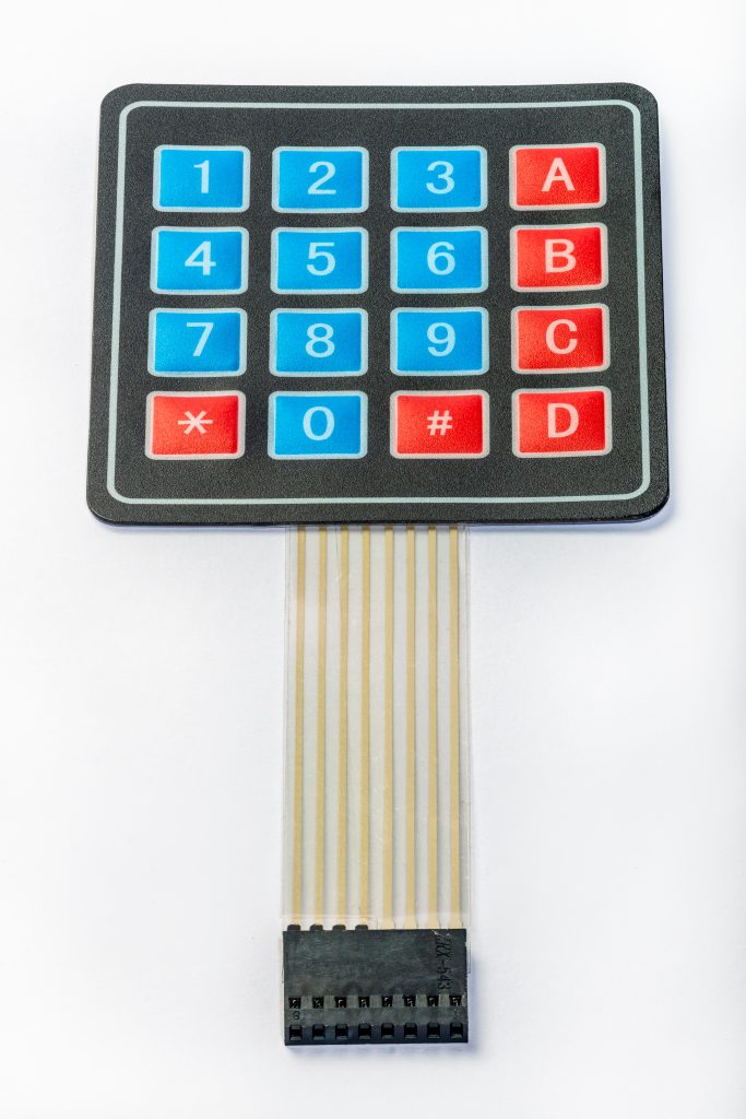
1. Keypad structure:
In a keypad, push button switches are arranged in rows and columns. For a 4×4 keypad 16 switches are used and to connect to microcontroller we need 16 inputs pins. But the arrangement is changed by connecting switches in a special way. Now we need only 8 pins of microcontroller to connect keypad to it.
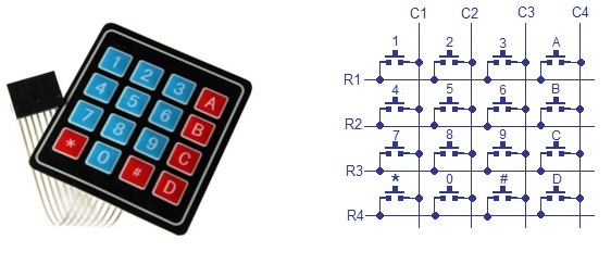
The status of each key/switch is determined by Scanning the rows or columns. The column pins (Col 1–Col4) are connected to the microcontroller as the inputs pinsand the rows pins (Row 1–Row 4) are connected to the output pins of the microcontroller. Normally, all the column pins are pulled high by internal or external pull up resistors. Now we can read the status of each switch through scanning.
2. Reading keypad:
Scanning is done in a different way. Columns pins are used as input pins, and rows pins are used as output. If a low logic is given to all the Rows and high logic is given to each Column.
For finding Column number:
- When a switch/key is pressed, the corresponding row and column will get short.
- Output of the corresponding column goes to go low.
- Since we have made all the rows zero so this gives the column number of the pressed key.
For Finding Row number:
- After the detection of column number, the controller set’s all the rows to high.
- Each row is one by one set to zero by the microcontroller and the earlier detected column is checked and obviously it becomes zero.
- The row due to which the column gets zero is the row number of the pressed key.
3. Keypad pinout:
The pinout of 4×4 keypad as following (for this model only):
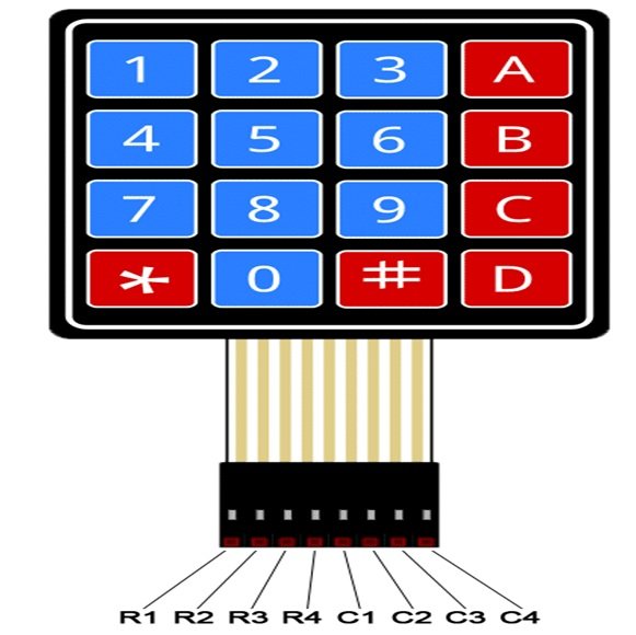
Where R stands for Row and C stands for Column.
4. Connection:
The connection of keypad with display as following:
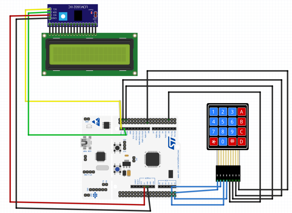
The connection as following:
| Keypad | STM32F4xx |
| R0 to R3 | PC0 to PC3 |
| C0 to C3 | PC4 to PC7 |
The LCD is connected to I2C bus to PB8 and PB9.
5. Initializing the Pins:
We start off by creating source and header file with name of keypad.c and keypad.h representative.
Within the header, put the header guard as following:
#ifndef KEYPAD_H_
#define KEYPAD_H_

#endif /* KEYPAD_H_ */
Within the guard, include stdint as following:
#include "stdint.h"
Declare the following two functions:
void keypad_init(void);


char keypad_read();
Hence, the header file as following:
#ifndef KEYPAD_H_
#define KEYPAD_H_

#include "stdint.h"


void keypad_init(void);


char keypdat_read();


#endif /* KEYPAD_H_ */
Now, to source file.
Within the source file, include both the header files for stm32f4xx.h and keypad as following:
#include "stm32f4xx.h"

#include "keypad.h"
To initialize the pins, the following steps are required:
- Enable clock access to GPIOC.
- Set PC0 to PC3 as input.
- Enable internal pullup resistor for PC0 to PC3.
- Set PC4 to PC7 as output.
- Set PPC4 to PC7 as high.
Hence, the init function as following:
void keypad_init(void)
{

	/*Enable clock access to GPIOC*/
	RCC->AHB1ENR|=RCC_AHB1ENR_GPIOCEN;

	/*Set PC0 to PC3 as input*/
	GPIOC->MODER &= ~(GPIO_MODER_MODE0|GPIO_MODER_MODE1|GPIO_MODER_MODE2|GPIO_MODER_MODE3);

	/* Activate internal pullup resistor for PC0 to PC3*/
	GPIOC->PUPDR|=GPIO_PUPDR_PUPD0_0|GPIO_PUPDR_PUPD1_0|GPIO_PUPDR_PUPD2_0|GPIO_PUPDR_PUPD3_0;

	/*Set PC4 to PC7 as output*/
	GPIOC->MODER |= GPIO_MODER_MODE4_0|GPIO_MODER_MODE5_0|GPIO_MODER_MODE6_0|GPIO_MODER_MODE7_0;

	GPIOC->MODER &=~( GPIO_MODER_MODE4_1|GPIO_MODER_MODE5_1|GPIO_MODER_MODE6_1|GPIO_MODER_MODE7_1);

	/*Set PC4 to PC7 as high*/

	GPIOC->BSRR = GPIO_BSRR_BS4|GPIO_BSRR_BS5|GPIO_BSRR_BS6|GPIO_BSRR_BS7;
}
Read keypad function shall be implemented in part 2.
Stay tuned.
Happy coding 🙂
Add Comment