
In this guide, we shall see how to configure the core of STM32F103 and make it to run at 72MHz which is the maximum core frequency for F103C8.
In this guide, we shall cover the following:
- Getting the correct parameters from CubeMX.
- Setting the core frequency using registers.
- Validating the frequency.
1. Getting the correct parameters from CubeMX:
Open STM32CubeMX and select the STM32F103 as the main mcu.
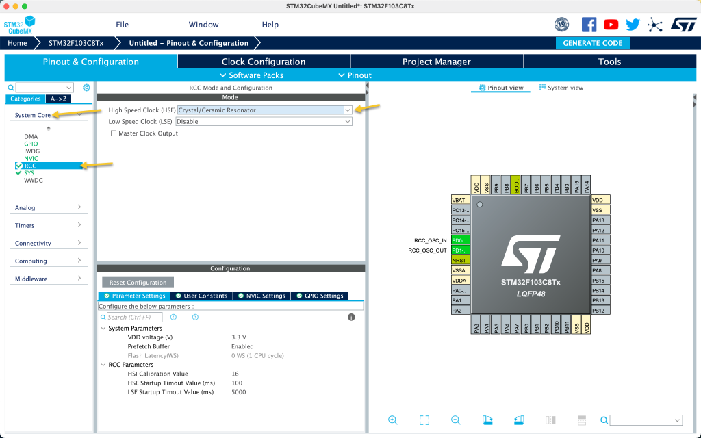
After selecting the MUC, head to System Core, RCC and select High speed oscillator as external ceramic oscillator:
Then from Clock configuration, set the external oscillator to 8MHz, PLL source to be HSE, System Clock Mux from PLL and set the frequency to 72 and hit enter:
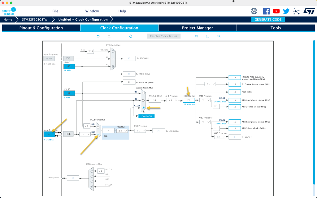
After the configuration is finished, take note for the following parameters:
- PLLMUL=9
- AHB Prescaler 1
- APB1 Prescaler 2
- APB2 Prescaler 1
Head back to RCC section is System Core and notice the prefetch if it enabled and flash latency:
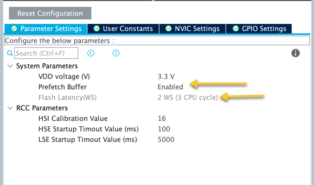
In this case, the prefetch is enabled and flash latency is 2WS.
Now, we have all the required information. Next, we shall configure the required register.
2. Setting the core frequency using registers:
We start off by creating new source file and name it as core.c.
Within core.c, include the main chip header as following:
#include "stm32f1xx.h"
Declare the following function:
void SystemInit(void)
This function will be called once the mcu is started before the main function starts.
Within the function:
- Set the PLLMUL to 9 as following:
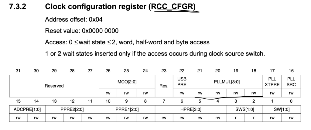
	  RCC->CFGR &= ~RCC_CFGR_PLLMULL_Msk; //Clear
	  RCC->CFGR |= (0x7UL << RCC_CFGR_PLLMULL_Pos);
- Set the USB prescaler to 1.5:
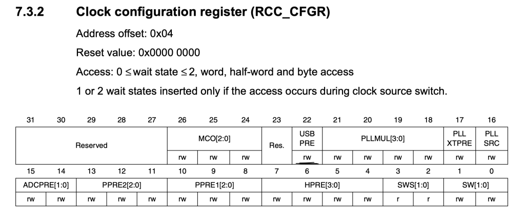
	  //USB Prescaler = 1.5
	  RCC->CFGR &= ~(0x1UL << 22);
- Enable External oscillator and wait until it is ready:
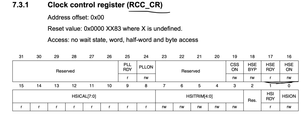
	  //Enable HSE Clock
	  RCC->CR |= RCC_CR_HSEON;
	  //Wait for HSE to be stable and ready to use
	  while((RCC->CR & RCC_CR_HSERDY) == 0);
- Select the source as PLL:
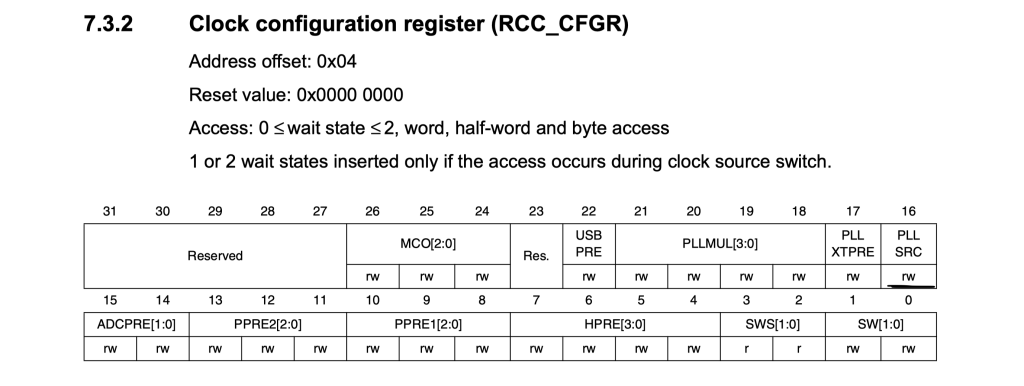
	  //HSE as PLL source
	  RCC->CFGR |= RCC_CFGR_PLLSRC;
- Turn the PLL and wait until it is read:
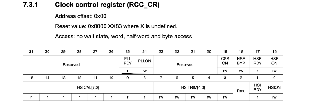
//Enable the PLL
	  RCC->CR |= RCC_CR_PLLON;
	  //Wait until PLL is ready
	  while((RCC->CR & RCC_CR_PLLRDY) == 0);
- Enable prefetch and set the latency of the flash to 2WS:
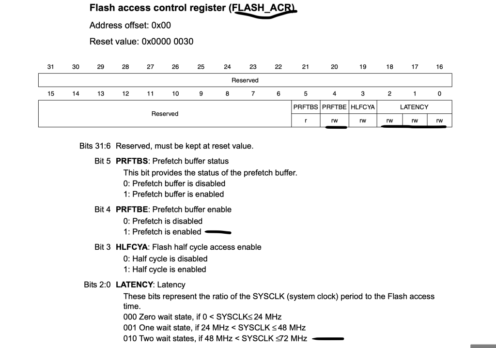
	  //Flash pre-fetch enable and wait-state=2
	  //0WS: 0-24MHz
	  //1WS: 24-48MHz
	  //2WS: 48-72MHz
	  FLASH->ACR = FLASH_ACR_PRFTBE | FLASH_ACR_LATENCY_1;
- Select PLL as the main clock source and wait until the source is set:
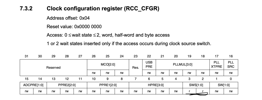
      //Select PLL as main System Clock source
	  RCC->CFGR &= ~RCC_CFGR_SW;
	  RCC->CFGR |= RCC_CFGR_SW_1;
	  //Wait until PLL system source is active
	  while((RCC->CFGR & RCC_CFGR_SWS) != RCC_CFGR_SWS_1);
- Set the AHB, APB1 and APB2 prescaler and ADC prescaler to 12:
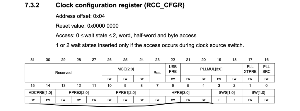
//AHB Prescaler = 1
	  RCC->CFGR &= ~RCC_CFGR_HPRE;
	  //APB1 divider=2
	  RCC->CFGR &= ~RCC_CFGR_PPRE1;
	  RCC->CFGR |= RCC_CFGR_PPRE1_2;
	  //APB2 divider=1
	  RCC->CFGR &= ~RCC_CFGR_PPRE2;
	  //ADC prescalar = 12
	  RCC->CFGR &= ~RCC_CFGR_ADCPRE;
	  RCC->CFGR |= RCC_CFGR_ADCPRE_1;
Thats all for the configuration.
3. Validating the frequency:
Now, we shall validate the frequency using timer2 in output compare. For more details check this topic.
#include "stm32f1xx.h"


int main(void)
{
	RCC->APB2ENR|=RCC_APB2ENR_IOPAEN;

		/*Configure PA0 as Output Alternate Push/Pull */
		GPIOA->CRL|=GPIO_CRL_MODE0;
		GPIOA->CRL|=(GPIO_CRL_CNF0_1);
		GPIOA->CRL&=~(GPIO_CRL_CNF0_0);

		/*Don't remap the pin*/
		AFIO->MAPR&=~AFIO_MAPR_TIM2_REMAP;


		/*Enable clock access to timer2*/
		RCC->APB1ENR|=RCC_APB1ENR_TIM2EN;

		/*Configure timer2*/
		TIM2->PSC=7200-1;
		TIM2->ARR=10000-1;
		TIM2->CCMR1|=TIM_CCMR1_OC1M_0|TIM_CCMR1_OC1M_1;
		TIM2->CCER|=TIM_CCER_CC1E;
		TIM2->CR1|=TIM_CR1_CEN;

	while(1)
	{


	}
}
You should get 1 second toggle rate as shown in this video:
Happy coding 🙂
Add Comment