In the previous guide (here), we took a look how to configure the UART to transmit and receive data to/from PC using DMA. The limitation that we shall wait until the buffer is filled before we print the the received characters. In this guide, we shall use IDLE Line interrupt to receive unknown length of characters.
In this guide, we shall cover the following:
- What is IDLE line.
- Configure UART for IDLE interrupt.
- Support functions.
- Code.
- Demo.
1. What is IDLE Line:
The use of IDLE is mostly related to synchronous communications (although you could use this concepts in asynchronous mode as well).
Because there is a continuous bitstream flowing on the line in synchronous mode, there is no way to send nothing – To be able to do that, the IDLE pattern (normally all ones) is often used. It simply means there is no data on the line.
2. Configure UART for IDLE interrupt:
In order to enable IDLE line interrupt for UART, we need to set the IDLEIE bit in CR1:
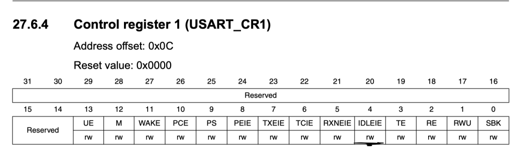
USART2->CR1|=USART_CR1_IDLEIE;
Then enable USART2 interrupt in the NVIC as following:
	/*Enable USART2 interrupt in NVIC*/
	NVIC_EnableIRQ(USART2_IRQn);
For the interrupt handler:
The following is performed:
- Check if the source is the IDLE line.
- If it is, set idle variable to 1
- Clear the flag by reading the DR register.
void USART2_IRQHandler(void)
{
	if (USART2->SR & USART_SR_IDLE)
		{

			idle=1;
			/*Clearing sequence:
			 * Read the SR register (Already done in if condition)
			 * Read the DR register
			 * */
			(void)USART2->DR;
		}
}
3. Support Function:
The support function is reseting the buffer. The following is used to reset the buffer:
- Disable the DMA.
- Set the buffer to NULL using memset.
- Reload the buffer to the DMA.
- Enable the DMA again.
void reset_buffer()
{
	/*Disable DMA*/
	DMA1_Channel6->CCR&=~DMA_CCR_EN;
	while((DMA1_Channel6->CCR) &DMA_CCR_EN);
	memset(rc_data, 0, rc_data_size);
	DMA1_Channel6->CNDTR=rc_data_size;
	DMA1_Channel6->CCR|=DMA_CCR_EN;
}
4. Code:
The code as following:
#include "stm32f1xx.h"
#include "stdio.h"
#include "string.h"


#define Perpher_CLK 8000000
#define Baudrate	115200


static uint16_t compute_uart_bd(uint32_t PeriphClk, uint32_t BaudRate)
{
	return ((PeriphClk + (BaudRate/2U))/BaudRate);
}


static void uart_set_baudrate(USART_TypeDef *USARTx, uint32_t PeriphClk,  uint32_t BaudRate)
{
	USARTx->BRR =  compute_uart_bd(PeriphClk,BaudRate);
}


void uart2_write(int ch)
{
  /*Make sure the transmit data register is empty*/
	while(!(USART2->SR & USART_SR_TXE)){}

  /*Write to transmit data register*/
	USART2->DR	=  (ch & 0xFF);
}

/*Retargeting printf*/
int __io_putchar(int ch){uart2_write(ch); return ch;}


#define rc_data_size 20
uint8_t rc_data[rc_data_size];

volatile uint8_t done=0,idle=0;


void reset_buffer();


int main(void)
{

	/*UART2 Pin configures*/

	//enable clock access to GPIOA
	RCC->APB2ENR|=RCC_APB2ENR_IOPAEN;
	//Enable clock access to alternate function
	RCC->APB2ENR|=RCC_APB2ENR_AFIOEN;

	/*Confgiure PA2 as output maximum speed to 50MHz
	 * and alternate output push-pull mode*/
	GPIOA->CRL|=GPIO_CRL_MODE2;

	GPIOA->CRL|=GPIO_CRL_CNF2_1;
	GPIOA->CRL&=~GPIO_CRL_CNF2_0;


	/*Configure PA3 as Input floating*/

	/*Set mode to be input*/
	GPIOA->CRL &=~(GPIO_CRL_MODE3);
	GPIOA->CRL|=GPIO_CRL_CNF3_0;
	GPIOA->CRL&=~GPIO_CRL_CNF3_1;


	/*Don't remap the pins*/
	AFIO->MAPR&=~AFIO_MAPR_USART2_REMAP;


	/*USART2 configuration*/

	//enable clock access to USART2

	RCC->APB1ENR|=RCC_APB1ENR_USART2EN;

	//Transmit Enable
	USART2->CR1 |= USART_CR1_TE;

	//Enable receiver
	USART2->CR1 |= USART_CR1_RE;

	/*Enable IDLE Line interrupt*/

	USART2->CR1|=USART_CR1_IDLEIE;

	/*Enable USART2 interrupt in NVIC*/
	NVIC_EnableIRQ(USART2_IRQn);

	/*Enable DMA for receiver*/
	USART2->CR3|=USART_CR3_DMAR;

	/*Set baudrate */
	uart_set_baudrate(USART2,Perpher_CLK,Baudrate);

	/*DMA configuration*/

	RCC->AHBENR|=RCC_AHBENR_DMA1EN;

	DMA1_Channel6->CCR|=DMA_CCR_MINC|DMA_CCR_CIRC|DMA_CCR_TCIE;

	NVIC_EnableIRQ(DMA1_Channel6_IRQn);

	/*Set the peripheral address to be USART2->DR*/
	DMA1_Channel6->CPAR=(uint32_t)&USART2->DR;

	DMA1_Channel6->CMAR=(uint32_t)rc_data;

	DMA1_Channel6->CNDTR=rc_data_size;

	DMA1_Channel6->CCR|=DMA_CCR_EN;


	//Enable UART
	USART2->CR1 |= USART_CR1_UE;


	while(1)
	{
		while(idle==0);
		printf("Received data:\"%s\"\r\n",rc_data);
		reset_buffer();
		idle=0;


	}
}


void reset_buffer()
{
	/*Disable DMA*/
	DMA1_Channel6->CCR&=~DMA_CCR_EN;
	while((DMA1_Channel6->CCR) &DMA_CCR_EN);
	memset(rc_data, 0, rc_data_size);
	DMA1_Channel6->CNDTR=rc_data_size;
	DMA1_Channel6->CCR|=DMA_CCR_EN;
}

void DMA1_Channel6_IRQHandler(void)
{
	if(DMA1->ISR &DMA_ISR_TCIF6)
	{
		done=1;
		DMA1->IFCR=DMA_IFCR_CTCIF6;
	}

}

/*USART2 interrupt handler*/

void USART2_IRQHandler(void)
{
	if (USART2->SR & USART_SR_IDLE)
		{

			idle=1;
			/*Clearing sequence:
			 * Read the SR register (Already done in if condition)
			 * Read the DR register
			 * */
			(void)USART2->DR;
		}
}
5. Demo:
Happy coding 🙂
2 Comments
Is there a way to detect the number of bytes received?
you can read DMA1_Channel6->CNDTR register
then subtract the register value from rc_data_size.
This way, you will get the received characters.
Add Comment