In the previous guide (here), we took a look how to use ADC in DMA mode to acquire the data from two channels. In this guide, we shall see how to configure the ADC to be triggered by timer.
In this guide, we shall cove the following:
- Timer triggered ADC with DMA.
- Connection.
- Code.
- Results.
1. Timer triggered ADC with DMA:
We start off by enabling clock access to port A and set PA0 and PA1 to analog mode:
	//enable clock access to GPIOA
	RCC->APB2ENR|=RCC_APB2ENR_IOPAEN;
	/*Set PA0 to analog Mode*/
	GPIOA->CRL&=~GPIO_CRL_CNF0;
	GPIOA->CRL&=~GPIO_CRL_MODE0;


	/*Set PA1 to analog Mode*/
	GPIOA->CRL&=~GPIO_CRL_CNF1;
	GPIOA->CRL&=~GPIO_CRL_MODE1;
Enable clock access to ADC1:
	/*Enable clock access to ADC1*/
	RCC->APB2ENR|=RCC_APB2ENR_ADC1EN;
Set the trigger source to be external and the source to be TIM3_TRGO:
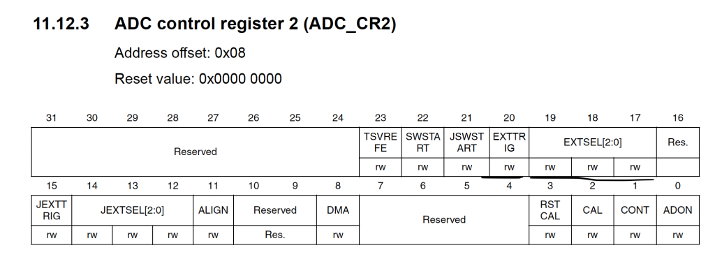
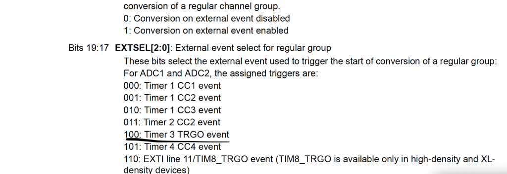
	/*Set trigger mode to be external*/
	ADC1->CR2|=ADC_CR2_EXTTRIG;

	/*Set external trigger to be TIM2_CC2 event*/

	ADC1->CR2|=ADC_CR2_EXTSEL_2;
Disable continuous mode:
	/*Disable Continuous mode */

	ADC1->CR2&=~ADC_CR2_CONT;
Enable scan mode:
/*Enable scan mode*/
	ADC1->CR1|=ADC_CR1_SCAN;
Enable DMA for ADC:
/*Enable DMA for ADC*/
	ADC1->CR2|=ADC_CR2_DMA;
Set the following:
- Length to be 2.
- Sample sequence is CH0 then CH1.
/*Set length to 2*/
	ADC1->SQR1|=(ADC_Channels<<ADC_SQR1_L_Pos);

	/*Sample sequence
	 * PA0 then PA1
	 * */
	ADC1->SQR3|=(ADC_CH0<<ADC_SQR3_SQ1_Pos)|(ADC_CH1<<ADC_SQR3_SQ2_Pos);
DMA part is the same as previous part:
	/*Enable Clock access to DMA1*/
	RCC->AHBENR|=RCC_AHBENR_DMA1EN;

	/*DMA1_Channel1 is for ADC1*/

	DMA1_Channel1->CCR|=DMA_CCR_MSIZE_0|DMA_CCR_PSIZE_0|DMA_CCR_MINC
			|DMA_CCR_CIRC;

	DMA1_Channel1->CNDTR=2;

	DMA1_Channel1->CPAR=(uint32_t)(&ADC1->DR);

	DMA1_Channel1->CMAR=(uint32_t)(adc_data);

	DMA1_Channel1->CCR|=DMA_CCR_EN;
Now, for the timer configuration.
Since we set the trigger source to be TIM3, we need to enable clock access to it.
From the datasheet, we can find that TIM3 is connected to APB1:
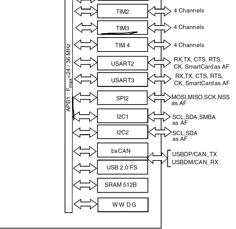
RCC->APB1ENR|=RCC_APB1ENR_TIM3EN;
Set the master mode selection to be Compare – OC1REF signal is used as trigger output (TRGO):
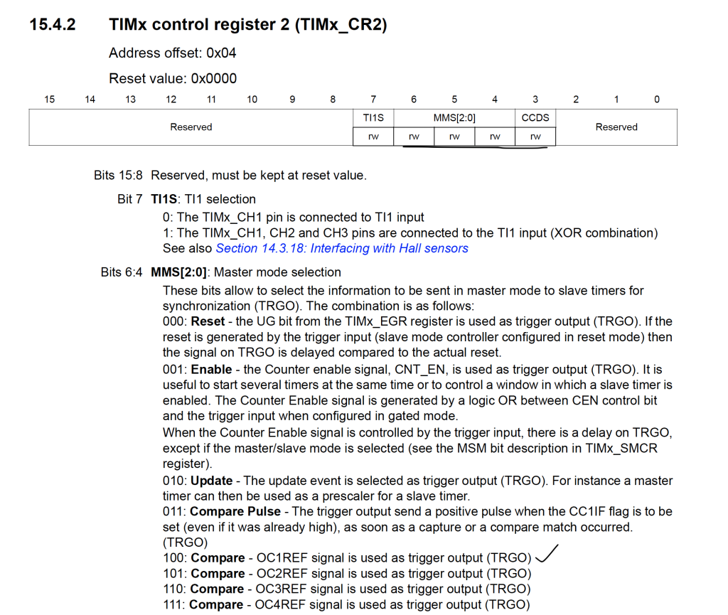
TIM3->CR2|=TIM_CR2_MMS_1;
Set the prescaler and ARR to be 7999 and 999 respectively:
	TIM3->PSC=8000-1;
	TIM3->ARR=1000-1;
Finally enabled the timer:
TIM3->CR1|=TIM_CR1_CEN;
Final step is to launch the ADC:
	/*Power up the adc*/
	ADC1->CR2|=ADC_CR2_ADON;

	/*Wait a little bit*/

	for (int i=0;i<1000;i++);
	/*Launch the ADC*/
	ADC1->CR2|=ADC_CR2_ADON;
2. Connection:
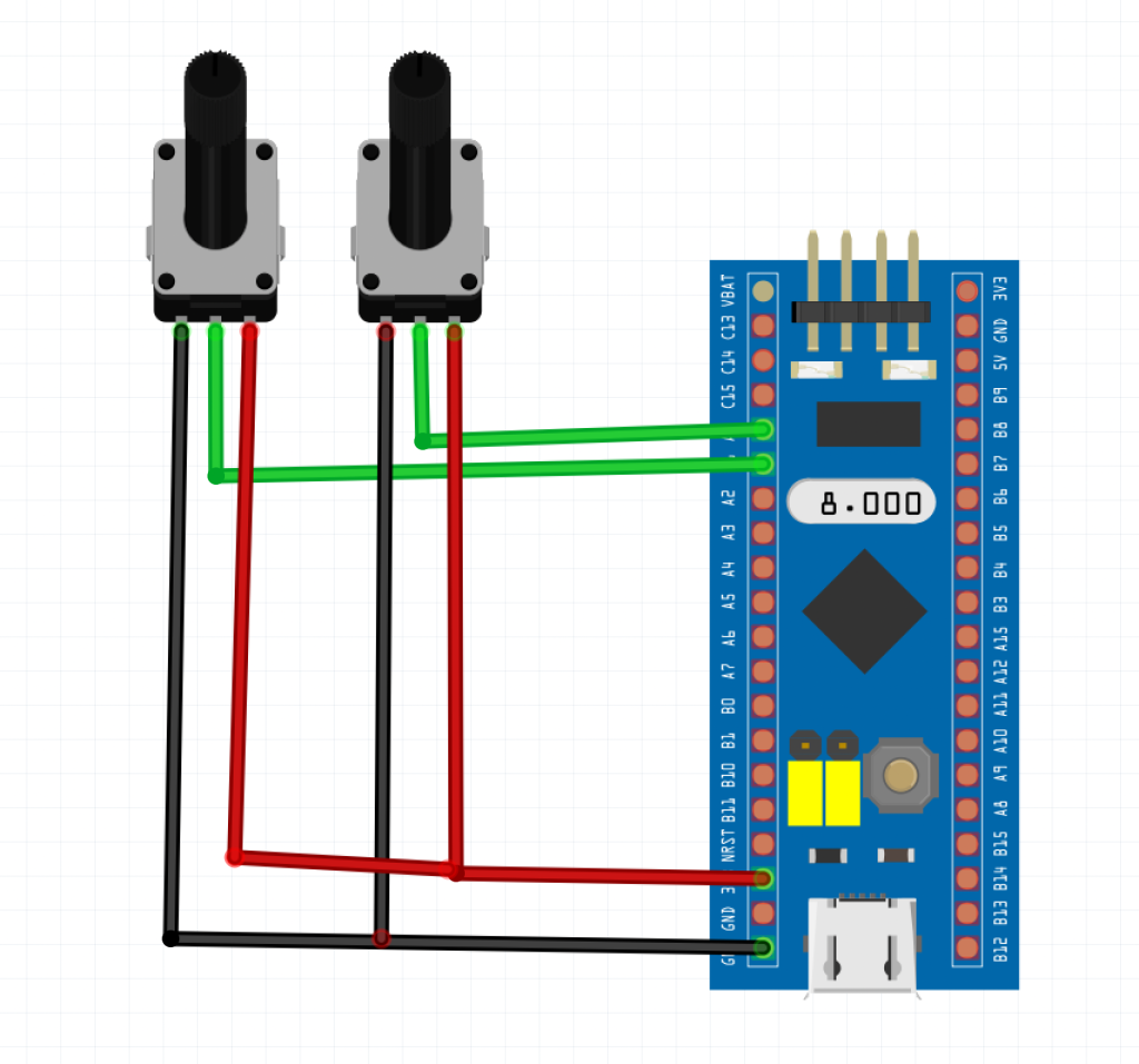
The following are required:
- STM32F103C8.
- 2x 10KOhm potentiometer.
The connection as following:
2 Comments
Please, I have followed up, I guess most basic setup I understood. However, I need clarification about the timer trigger.
Does the timer trigger to start a group ch1,2,3 or it trigger to start only a single ADC conversion and will require 3periods to complete 3channels?
For example,
If I have 3 channels and each conversion is 239.5+12.5.
What will be the prescale and ARR period if I need 1ms sampling spacing channels?
Hi,
The timer will trigger the ADC to start conversion of all channel (since scan mode is enabled) once the period of the timer is over.
Regarding your question, the setup will be complicated to achieve your desired spacing of 1ms between each channel.
Add Comment