In the previous guide (here), we took a look how to configure ADC of STM32F103 to do one conversion only.
In this guide, we shall use continuous mode for the ADC.
In this guide, we shall cover the following:
- Single vs continuous conversion mode.
- Code.
- Results.
1. Single Vs Continuous conversion mode:
2.1 Single Conversion:
In Single conversion mode the ADC does one conversion. This mode is started either by setting the ADON bit in the ADC_CR2 register (for a regular channel only) or by external trigger (for a regular or injected channel), while the CONT bit is 0.
2.2 Continuous Conversion:
In continuous conversion mode ADC starts another conversion as soon as it finishes one. This mode is started either by external trigger or by setting the ADON bit in the ADC_CR2 register, while the CONT bit is 1.
2. Code:
From the previous guide, we shall take the code and modify it.
In order to enable continuous mode, we need to set CON bit in CR2 to 1:
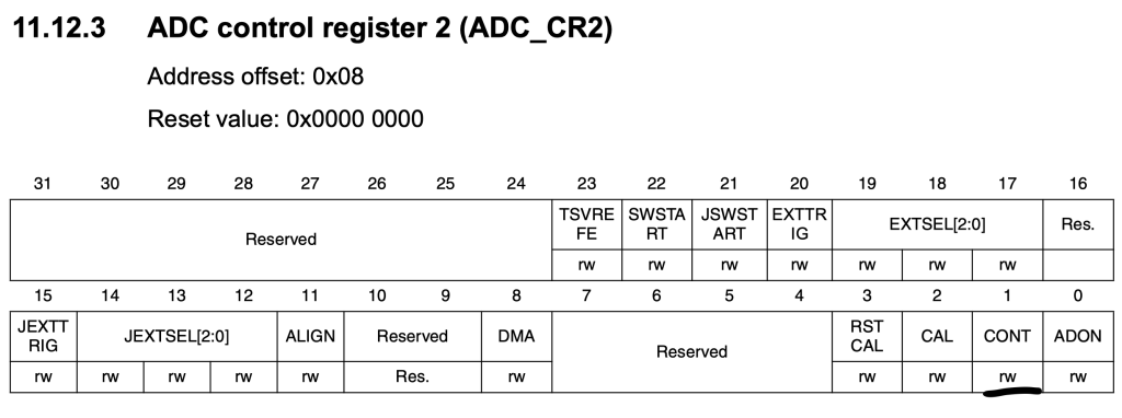
	/*Enable Continuous mode */

	ADC1->CR2|=ADC_CR2_CONT;
And move the launching adc to main section as following:
	/*Power up the adc*/
	ADC1->CR2|=ADC_CR2_ADON;

	/*Wait a little bit*/

	for (int i=0;i<1000;i++);
	/*Launch the ADC*/
	ADC1->CR2|=ADC_CR2_ADON;

	/*Launch the ADC conversion*/
	ADC1->CR2|=ADC_CR2_SWSTART;
Within while 1 loop:
- Wait for EOC of conversion.
- Read the DR register.
while(1)
	{
		/*wait for EOC*/
		while(!(ADC1->SR &ADC_SR_EOC));
		adc_data=ADC1->DR;

	}
Hence, the entire code as following:
#include "stm32f1xx.h"


uint32_t adc_data;

int main()
{
	/*Enable clock access to GPIOA*/
	//enable clock access to GPIOA
	RCC->APB2ENR|=RCC_APB2ENR_IOPAEN;
	/*Set PA0 to analog Mode*/
	GPIOA->CRL&=~GPIO_CRL_CNF0;
	GPIOA->CRL&=~GPIO_CRL_MODE0;

	/*Enable clock access to ADC1*/
	RCC->APB2ENR|=RCC_APB2ENR_ADC1EN;

	/*Set the trigger to be software mode*/
	ADC1->CR2 |= (7UL << ADC_CR2_EXTSEL_Pos);

	/*Enable Continuous mode */

	ADC1->CR2|=ADC_CR2_CONT;

	/*Power up the adc*/
	ADC1->CR2|=ADC_CR2_ADON;

	/*Wait a little bit*/

	for (int i=0;i<1000;i++);
	/*Launch the ADC*/
	ADC1->CR2|=ADC_CR2_ADON;

	/*Launch the ADC conversion*/
	ADC1->CR2|=ADC_CR2_SWSTART;

	while(1)
	{
		/*wait for EOC*/
		while(!(ADC1->SR &ADC_SR_EOC));
		adc_data=ADC1->DR;

	}

}
3. Results:
Open new debug session and put adc_data into live expression and you should get the results.
Add Comment