In this guide, we shall learn how to use the ADC of the STM32 for single channel Single Conversion mode using only registers.
The ADC is commonly used to measure the voltage from a sensor for example temperature sensor such as LM35 which can provide voltage proportional to the temperature.
This guide will cover the following
- What is the ADC
- Required Parts
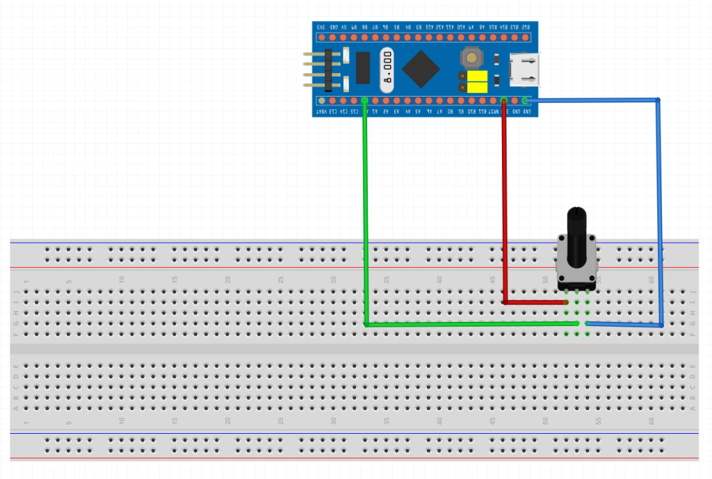
- Schematic
- Code
- Results
1.1 What is the ADC
In electronics, an analog-to-digital converter (ADC, A/D, or A-to-D) is a system that converts an analog signal, such as a sound picked up by a microphone or light entering a digital camera, into a digital signal that can be read by STM32.
ADCs can vary greatly between microcontroller. The ADC on the STM32F103 is a 12-bit ADC meaning it has the ability to detect 4096(2^12) discrete analog levels (which is also called Resolution). Some microcontrollers have 8-bit ADCs (2^8 = 256 discrete levels) and some have 16-bit ADCs (2^16 = 65,536 discrete levels).
The way an ADC works is fairly complex. There are a few different ways to achieve this feat (see Wikipedia for a list), but one of the most common technique uses the analog voltage to charge up an internal capacitor and then measure the time it takes to discharge across an internal resistor. The microcontroller monitors the number of clock cycles that pass before the capacitor is discharged. This number of cycles is the number that is returned once the ADC is complete. Other methods used called Successive-approximation ADC which you can read about it in details from this wikipedia page (Link).
1.2 Relating ADC Value to Voltage
The ADC reports a ratio metric value. This means that the ADC assumes 3.3V is 4095 and anything less than 3.3V will be a ratio between 3.3V and 4095.
For example if the sensor has output voltage of 1.66V hence the ADC output will be (4095/3.3)*1.66=2059.
2 Required Parts
You will need the following parts:
- STM32F103C8T6.
- Potentiometer 10KOhm.
- Breadboard.
- Hookup wires.
The connection as following:
3. Code:
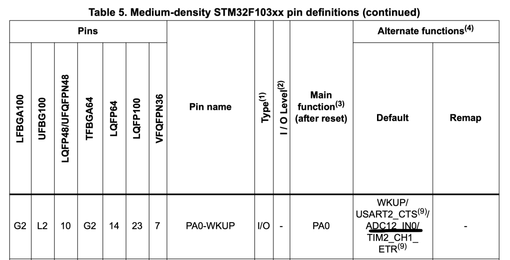
From the datasheet, we can find that PA0 is connected to ADC channel0:
Hence, we enable clock access to GPIOA as following:
RCC->APB2ENR|=RCC_APB2ENR_IOPAEN;
Configure PA0 as analog mode:
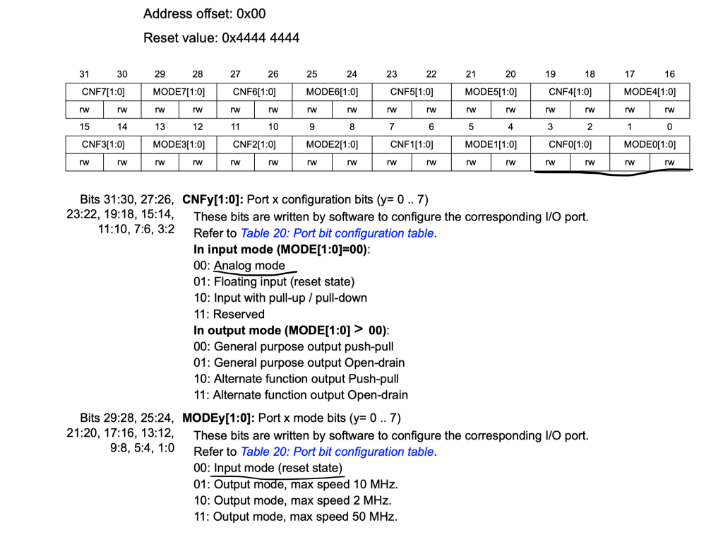
	/*Set PA0 to analog Mode*/
	GPIOA->CRL&=~GPIO_CRL_CNF0;
	GPIOA->CRL&=~GPIO_CRL_MODE0;
Thats all for GPIO configuration.
Next, ADC configuration.
To configure the ADC, first we need to enable clock access to ADC1. From the datasheet and the block diagram, we can find that ADC1 is connected to APB2 as following:
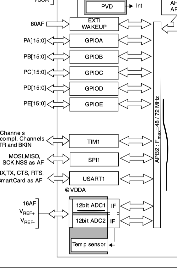
Hence, we can enable clock access to it as following:
	/*Enable clock accrss to ADC1*/
	RCC->APB2ENR|=RCC_APB2ENR_ADC1EN;
Next, we need to set the trigger source to be software trigger. From ADC Control Register 2 (ADCx_CR2) as following:
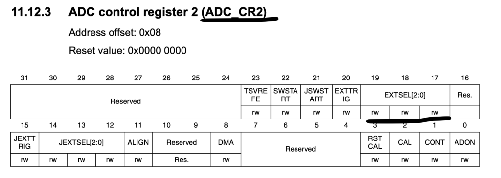
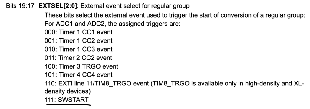
	/*Set the trigger to be software mode*/
	ADC1->CR2 |= (7UL << ADC_CR2_EXTSEL_Pos);
Finally, power up the ADC:
	/*Power up the adc*/
	ADC1->CR2|=ADC_CR2_ADON;
waste few cpu cycles (needed to ensure ADC is woke up):
	/*Wait a little bit*/
	for (int i=0;i<1000;i++);
Thats all for the configuration.
In order to read a single channel conversion, we need the following steps:
- Launch ADC.
- Start the conversion.
- Wait until the conversion is done.
- Read the data register.
To launch the ADC, you need to set ADON to 1:
		/*Relaunch the ADC*/
		ADC1->CR2|=ADC_CR2_ADON;
Then launch the conversion:
		/*Launch the ADC conversion*/
		ADC1->CR2|=ADC_CR2_SWSTART;
Wait until the ADC is finished by checking the EOC bit in SR (status register)
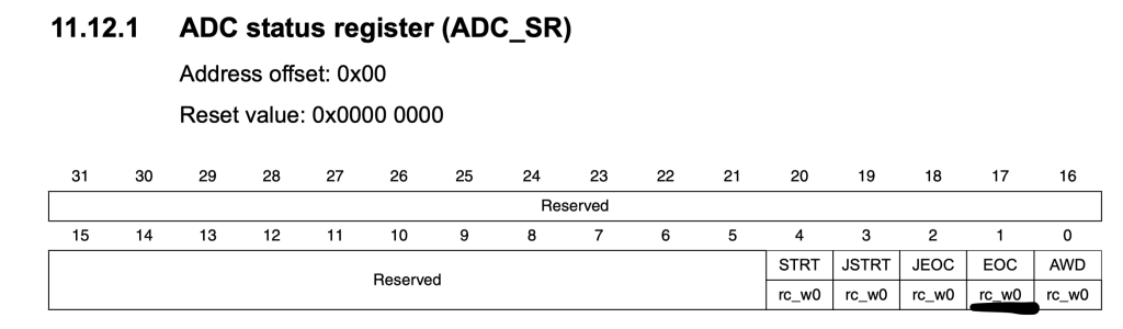
		/*wait for EOC*/

		while(!(ADC1->SR &ADC_SR_EOC));
Then read the ADC data register:
adc_data=ADC1->DR;
Hence, the entire code as following:
#include "stm32f1xx.h"


uint32_t adc_data;

int main()
{
	/*Enable clock access to GPIOA*/
	//enable clock access to GPIOA
	RCC->APB2ENR|=RCC_APB2ENR_IOPAEN;
	/*Set PA0 to analog Mode*/
	GPIOA->CRL&=~GPIO_CRL_CNF0;
	GPIOA->CRL&=~GPIO_CRL_MODE0;

	/*Enable clock accrss to ADC1*/
	RCC->APB2ENR|=RCC_APB2ENR_ADC1EN;

	/*Set the trigger to be software mode*/
	ADC1->CR2 |= (7UL << ADC_CR2_EXTSEL_Pos);
	/*Power up the adc*/
	ADC1->CR2|=ADC_CR2_ADON;


	/*Launch the ADC*/
	ADC1->CR2|=ADC_CR2_ADON;


	while(1)
	{
		/*Relaunch the ADC*/
		ADC1->CR2|=ADC_CR2_ADON;
		/*Launch the ADC conversion*/
		ADC1->CR2|=ADC_CR2_SWSTART;

		/*wait for EOC*/

		while(!(ADC1->SR &ADC_SR_EOC));

		adc_data=ADC1->DR;

	}

}
4. Results:
Happy coding 🙂
Add Comment