
In the previous guide here, we took a look how to configure a pin as output and blink an LED. In that guide, we used crude delay of for loop to blink the LED. In this guide, we shall use timer to create precise delay ranging from 1 millisecond all the way to 65 seconds.
In this guide, we shall cover the following:
- What is timer and how it does work.
- Configure the timer to generate delay.
- Code.
- Demo.
1. What is timer and how it does work:
A Timer Module in its most basic form is a digital logic circuit that counts up every clock cycle. More functionalities are implemented in hardware to support the timer module so it can count up or down. It can have a Prescaler to divide the input clock frequency by a selectable value. It can also have circuitry for input capture, PWM signal generation, and much more as we’ll see in this tutorial.
Let’s consider a basic 16-Bit timer like the one shown below. As a 16-Bit time, it can count from 0 up to 65535. Every clock cycle, the value of the timer is incremented by 1. And as you can see, the Fsys is not the frequency that is incrementing the timer module. But it gets divided by the Prescaler, then it gets fed to the timer.

Basically, in timer mode, the TCNT register is incremented by 1 each clock cycle @ the following frequency (Fsys/PSC). This means if the Fsys is 80MHz & PSC is 1:1024, the TCNT gets incremented by 1 every 12.8μSec. Therefore, if you start this timer to count from 0 until it reaches overflow (at 65535), a flag will be set and starts over from zero.
2. Configure the time to generate delay:
Since STM32F103 has multiple timers, we shall use timer2 for this guide.
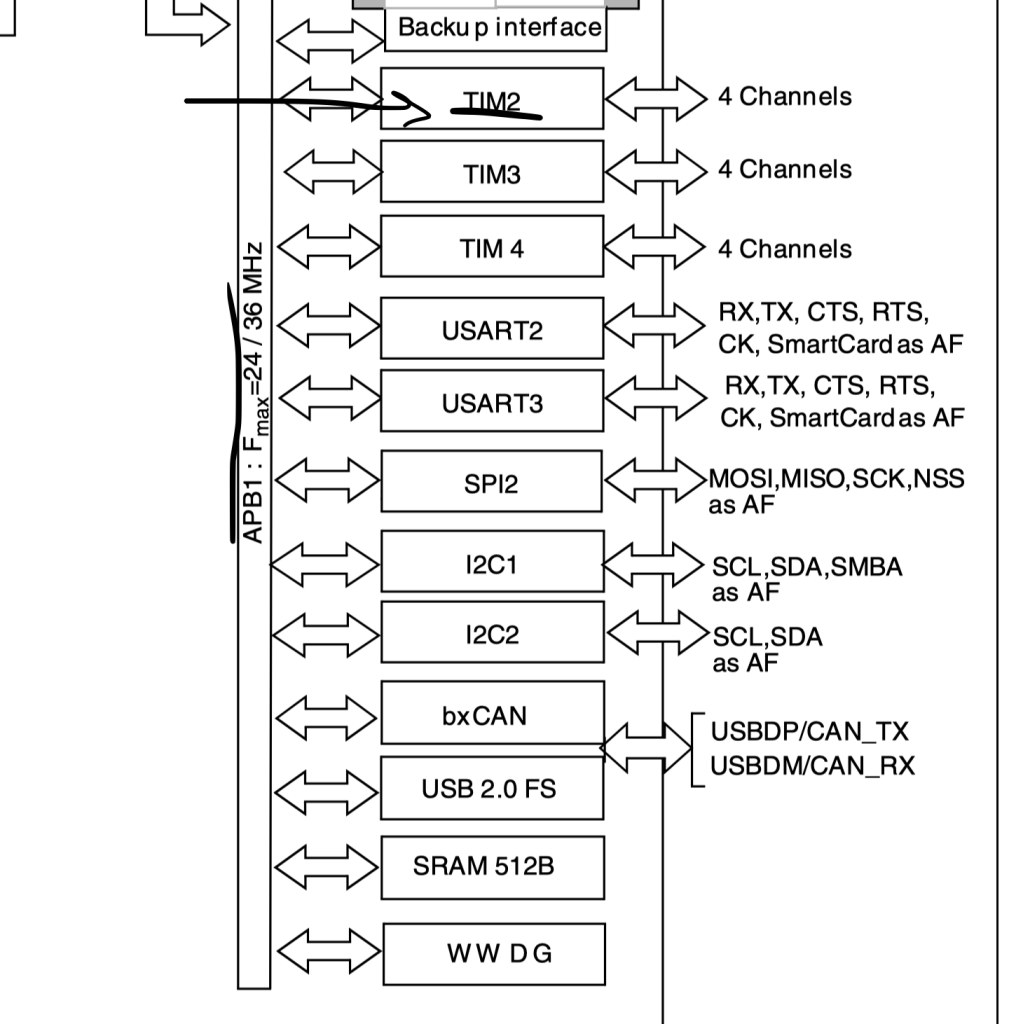
First, we need to enable clock access to TIM2 of STM32F1. In order to find which bus is connected to, we need the block diagram of STM32F103 which can be found in datasheet of STM32F1.
From the block diagram, we can find that TIM2 is connected to APB1 bus:
Hence, to enable clock access to TIM2:
/*Enable clock access to timer2*/
RCC->APB1ENR|=RCC_APB1ENR_TIM2EN;
Now, we can create a function named delay which takes ms as argument to indicate the amount to be delayed as following:
void delay(uint16_t ms)
Within the function, set the prescaller for the timer, since STM32F103C8 by default runs at 8MHz, we shall use prescaller of 8000-1 as following:
TIM2->PSC=8000-1; //8 000 000 Hz / 8 000 = 1 000 Hz (1 ms)
Set the Auto reload register the desired delay -1 :
TIM2->ARR=ms-1; // desired delay
Enable the timer from control register 1 (CR1):
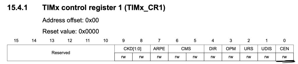
TIM2->CR1|=TIM_CR1_CEN;
Wait until the update flag is set in status register and then clear it once it is set:
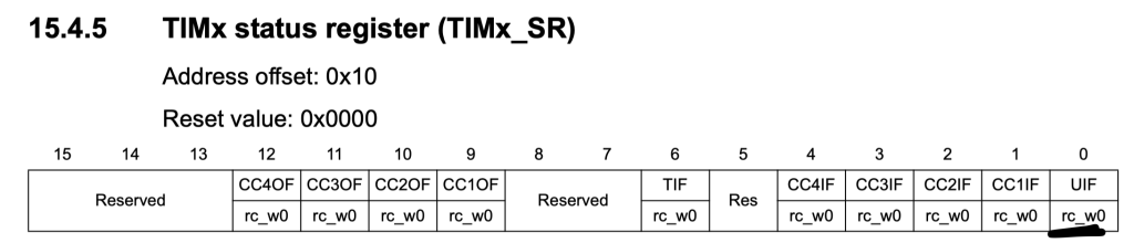
while(!(TIM2->SR&TIM_SR_UIF)){} //wait UIF to be set
TIM2->SR&=~TIM_SR_UIF; //reset UIF
Finally, disable the timer:
TIM2->CR1&=~TIM_CR1_CEN;
3. Code:
Hence, the entire code as following:
#include "stm32f1xx.h"


void delay(uint16_t ms)
{
	TIM2->PSC=8000-1; //8 000 000 Hz / 8 000 = 1 000 Hz (1 ms)
	TIM2->ARR=ms-1;   // desired delay
	TIM2->CR1|=TIM_CR1_CEN;
	while(!(TIM2->SR&TIM_SR_UIF)){} //wait UIF to be set
	TIM2->SR&=~TIM_SR_UIF; //reset UIF
	TIM2->CR1&=~TIM_CR1_CEN; // Disable the timer
}


int main(void)
{
	/*Enable clock access to GPIOA*/
	RCC->APB2ENR|=RCC_APB2ENR_IOPAEN;

	/*Configure PA0 as output*/
	GPIOA->CRL|=GPIO_CRL_MODE0;
	GPIOA->CRL&=~(GPIO_CRL_CNF0);

	/*Enable clock access to timer2*/
	RCC->APB1ENR|=RCC_APB1ENR_TIM2EN;


	while(1)
	{

		GPIOA->BSRR=GPIO_BSRR_BS0;//Set PA0 to high
		delay(1000); //Delay for 1 seconds
		GPIOA->BSRR=GPIO_BSRR_BR0; // Set PA0 to low
		delay(1000); // Delay for 1 seconds

	}
}
4. Demo:
Happy coding 🙂
2 Comments
Can you please provide Source code with stm32f1xx.h file
Hi,
please check this topic:
https://blog.embeddedexpert.io/?p=1332
Add Comment