In this guide, we shall use MCP4131 digital potentiometer with STM32 to vary the potentiometer using software.
In this guide, we shall cover the following:
- MCP4131.
- MCP4131 connection with STM32F4
- SPI Code.
- MCP4131 Code.
- Code.
- Demo.
1. MCP4131:
A digital potentiometer serves the same function as a potentiometer in hardware in that it varies resistance output. The difference is a digital potentiometer IC is controlled by software, while a regular potentiometer is controlled manually by a person.
Just like a regular potentiometer, a digital Pot IC comes in all different values of resistance.
The specific digital potentiometer we will use in this circuit is the MCP4131 IC. The MCP line of potentiometers come in 5KΩ, 10KΩ, 50KΩ, and 100KΩ, meaning you can purchase the IC in any of these maximum resistance values.
We will connect this digital pot IC to the STM32 microcontroller. Through software, we will then be able to change the resistance output at the wiper terminal of the potentiometer.
In this circuit, we will use an LED as our output device. We will operate the potentiometer from the highest resistance (when the LED will be off) to the lowest resitsance (where the LED will be the brightest) and cycle over and over again. This will serve to demonstrate all the resistances the potentiometer can offer and how it in turn can change an output.
By single, it’s meant that the chip contains a single potentiometer. Some digital pot ICS contain 2 potentiometers; these are called dual potentiometers. This means you could connect 2 or more output devices.
You can download the datasheet of the MCP4131 at the following link: MCP4131 Datasheet.
The MCP4131 operates on anywhere from 1.8V to 5.5V. Since the arduino provides 5V of power, it provides a perfect power source for the MCP4131 IC.
The MCP4131 changes resistance in a total of 129 steps, from 0 to 128, or in a total of 256 steps, from 0 to 255. However, we will operate ours in the 129-step interval. Thus, with a 100KΩ resistor, each step is an increment of approximately 775Ω (100K/129≈775Ω). With a 10KΩ resistor, each step is an increment of approximately 78Ω.
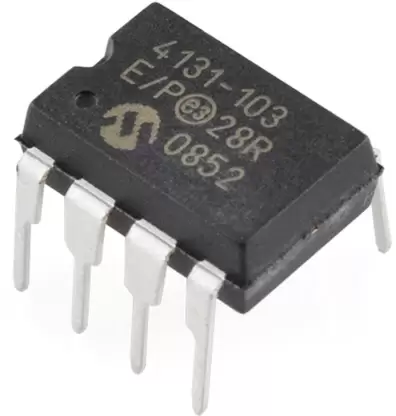
The MCP4131 is a 8-pin IC.
Its pinout is shown below. 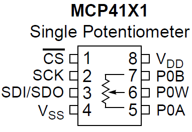
The table below summarizes the pins of the IC.
| MCP4131 Digital Potentiometer | ||
| Pin # | Pin Name | Description |
| 1 | CS | The CS, or Chip Select, pin is the SS (slave select) pin for the SPI interface. It is active low. 0V means the chip is selected and 5V means it is not selected. |
| 2 | SCLK | SCLK is the Shared/Serial Clock. It is the SPI clock line. |
| 3 | SDI/SDO | These pins are the serial data in and out, also known as the MOSI and MISO. |
| 4 | VSS | This is where ground is connected to. |
| 5 | PA0 | This is one terminal of the potentiometer. |
| 6 | PW0 | This is the wiper terminal of the potentiometer. |
| 7 | PB0 | This is one terminal of the potentiometer. |
| 8 | VCC | This is where the positive voltage source connects to. |
The MCP4131 digital potentiometer communicates via the Serial Peripheral Interface bus, or SPI bus.
Other ways of communicating are through the I2C bus and the serial UART bus.
The SPI us was originally created by Motorola and is a full-duplex serial communication standard that enables simultaneous bidirectional communication between a master device and one or more slave devices. Many times, SPI devices connect to one another, so that there is a master SPI and then slave SPI devices which communicate in sync with each other.
With the SPI, unlike the I2C bus, the SPI bus uses separate lines for sending and receiving data, and it employs an additional line for selecting which slave device you are talking to. This adds additional wires, but also eliminates needing different slave device addresses (since it’s hardware connected instead of through software). SPI runs at a faster speed than I2C and generally easier for beginners to work with.
SPI devices are synchronous, meaning that data is transmitted in sync with a shared clock signal (SCLK). Data can be shifted into the slave device on either the rising or the falling edge of the clock signal.
The STM32 has SPI support, containing a built-in library and hardware to communicate with a digitally controllable potentiometer.
The Chip Select pin decides which slave device you are communicating to. The Chip Select pin is also known as the Slave Select (SS) pin. If you just have one slave device, the chip select pin of that slave device has to drawn LOW to communicate with it, since the CS pin is an active low pin. After you are done communicating with the device, the CS pin should then be drawn HIGH.
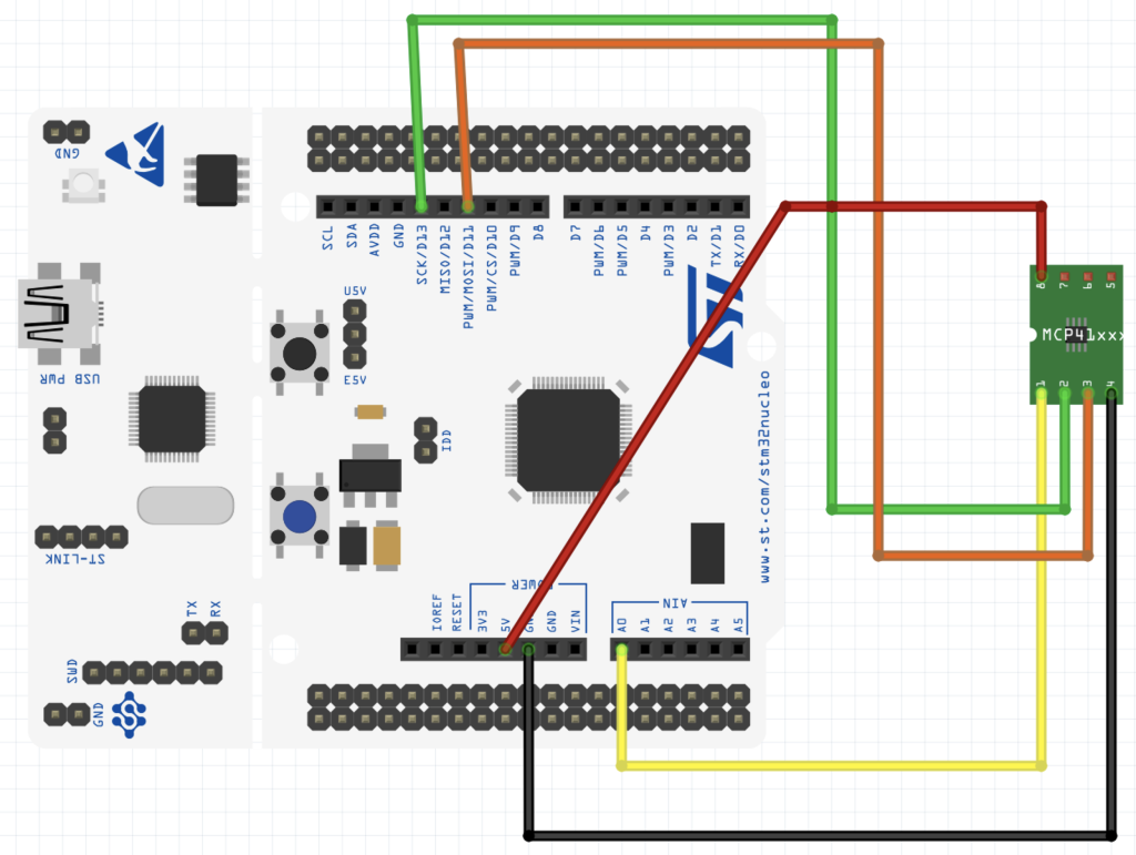
2. MCP4131 Connection with STM32F4:
3. SPI Configuration:
Create new source file and name it mcp4131_spi.c. The contain of the source file as following:
#include <mcp4131_spi.h>
#include "stm32f4xx.h"

void mcp4131_spi_pins_init()
{
	RCC->AHB1ENR|=RCC_AHB1ENR_GPIOAEN; //enable clock for GPIOA
	GPIOA->MODER|=GPIO_MODER_MODE0_0;
	GPIOA->MODER&=~GPIO_MODER_MODE0_1;

	GPIOA->MODER|=GPIO_MODER_MODE1_0;
	GPIOA->MODER&=~GPIO_MODER_MODE1_1;

	GPIOA->MODER |=(GPIO_MODER_MODE5_1|GPIO_MODER_MODE6_1|GPIO_MODER_MODE7_1);
	GPIOA->MODER &=~(GPIO_MODER_MODE5_0|GPIO_MODER_MODE6_0|GPIO_MODER_MODE7_0);

	GPIOA->AFR[0]|=(0x05<<20)|(0x05<<24)|(0x05<<28);
}

void mcp4131_spi_config()
{
	/*Enable clock access to SPI1 module*/
		RCC->APB2ENR |= RCC_APB2ENR_SPI1EN;

		/*Set clock to fPCLK/256*/
		SPI1->CR1 |=SPI_CR1_BR_0;
		SPI1->CR1 |=SPI_CR1_BR_1;
		SPI1->CR1 |=SPI_CR1_BR_2;


		/*Enable full duplex*/
		SPI1->CR1 &=~SPI_CR1_RXONLY;

		/*Set MSB first*/
		SPI1->CR1 &= SPI_CR1_LSBFIRST;

		/*Set mode to MASTER*/
		SPI1->CR1 |= SPI_CR1_MSTR;

		/*Set 8 bit data mode*/
		SPI1->CR1 &= ~SPI_CR1_DFF;

		/*Select software slave management by
		 * setting SSM=1 and SSI=1*/
		SPI1->CR1 |= SPI_CR1_SSM;
		SPI1->CR1 |= SPI_CR1_SSI;

		/*Enable SPI module*/
		SPI1->CR1 |= SPI_CR1_SPE;
}

void mcp4131_spi_transmit(uint8_t *data,uint32_t size)
{
	uint32_t i=0;

	while(i<size)
	{
		/*Wait until TXE is set*/
		while(!(SPI1->SR & (SPI_SR_TXE))){}

		/*Write the data to the data register*/
		SPI1->DR = data[i];
		i++;
	}
	/*Wait until TXE is set*/
	while(!(SPI1->SR & (SPI_SR_TXE))){}

	/*Wait for BUSY flag to reset*/
	while((SPI1->SR & (SPI_SR_BSY))){}

	/*Clear OVR flag*/
	(void)SPI1->DR;
	(void)SPI1->SR;
}


void mcp4131_enable(void)
{
	GPIOA->BSRR =GPIO_BSRR_BR9;

}

/*Pull high to disable*/
void mcp4131_disable(void)
{
	GPIOA->BSRR =GPIO_BSRR_BS9;
}
Create new header file and name it mcp4131_spi.h. The content of the header file as following:
#ifndef MCP4131_SPI_H_
#define MCP4131_SPI_H_

#include "stdint.h"

void mcp4131_spi_pins_init();
void mcp4131_spi_config();
void mcp4131_spi_transmit(uint8_t *data,uint32_t size);

void mcp4131_enable(void);
void mcp4131_disable(void);


#endif /* MCP4131_SPI_H_ */
For more information about SPI and how to configure the peripheral, please check this guide.
4. MCP4131 Code:
Since the chip uses SPI interface, we need to check timing diagram in order to figure out what the data shall be sent.
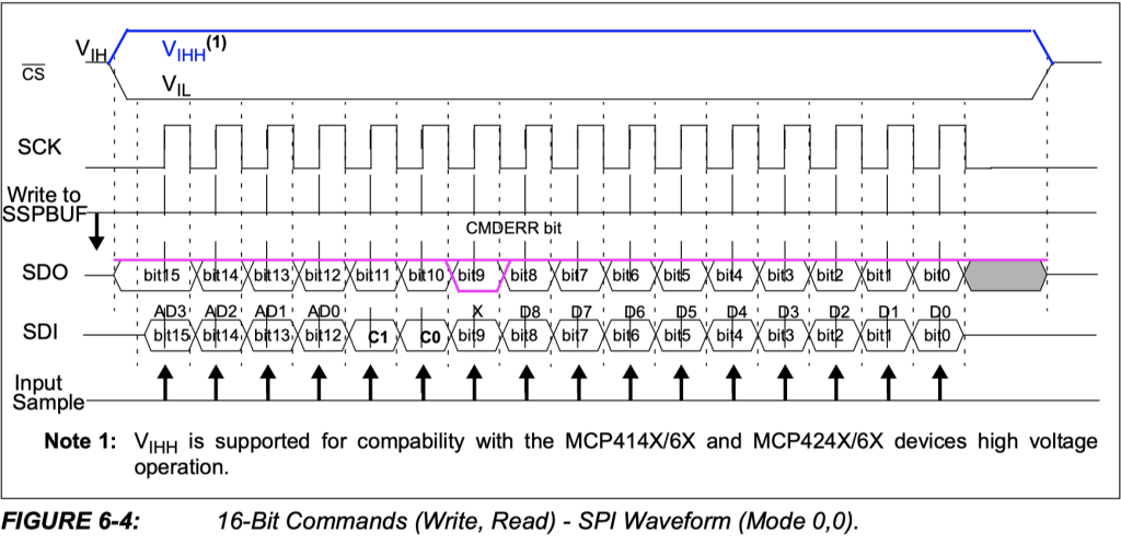
From the timing diagram, it turned out that we need first to send the address then followed by the pot value (7-bit ot 8-bit (model depending)).
Hence, to send the pot value, we need to send the address first which is 0x00 in this case, then the value (7-bit in this case):
void mcp4131_set_value (uint8_t value)
{
	if(value>128){value=128;}
	uint8_t data[2]={0,value};
	mcp4131_enable();
	mcp4131_spi_transmit(data,2);
	mcp4131_disable();

}
Hence, the entire code as following:
mcp4131_spi.c source code
#include "mcp4131.h"
#include "stm32f4xx.h"
#include "mcp4131_spi.h"


void mcp4131_init()
{
	mcp4131_spi_pins_init();
	mcp4131_spi_config();

}


void mcp4131_set_value (uint8_t value)
{
	if(value>128){value=128;}
	uint8_t data[2]={0,value};
	mcp4131_enable();
	mcp4131_spi_transmit(data,2);
	mcp4131_disable();
}
mcp4131_spi.h header file:
#ifndef MCP4131_H_
#define MCP4131_H_

#include "stdint.h"

void mcp4131_init();
void mcp4131_set_value (uint8_t value);


#endif /* MCP4131_H_ */
5. Code:
You may download the source code from here:
6. Demo:
Happy coding 🙂
Add Comment