In the previous guide (here), we took a look at I2C read mode to read set of registers from DS3231 RTC module using polling mode. In this guide, we shall use DMA to read those register.
In this guide, we shall cover the following:
- I2C configuration.
- I2C read using DMA.
- Code.
- Results.
1. I2C configuration:
First thing firs, declare a function that takes single argument for timing :
void i2c_dma_init(uint32_t timing){}Then we shall initialize the I2C as shown in previous guide:
#define AF4 0x04
	RCC->AHB1ENR|=RCC_AHB1ENR_GPIOBEN;
	GPIOB->MODER|=GPIO_MODER_MODER8_1|GPIO_MODER_MODER9_1;
	GPIOB->MODER&=~(GPIO_MODER_MODER8_0|GPIO_MODER_MODER9_0);
	GPIOB->OTYPER|=GPIO_OTYPER_OT8|GPIO_OTYPER_OT9;
	GPIOB->AFR[1]|=(AF4<<0)|(AF4<<4);

	RCC->APB1ENR|=RCC_APB1ENR_I2C1EN;
	I2C1->CR1 &=~I2C_CR1_PE;
	I2C1->TIMINGR=timing;
	I2C1->CR1 |=I2C_CR1_PE;
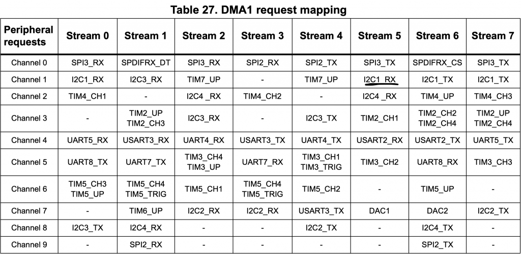
Now, we enable clock access to the DMA. Before that, we need to find which DMA, stream and channel for I2C1_RX. From the reference manual, DMA request table, DMA1_Stream5 Channel1 is for I2C1_TX. Hence we shall enable clock access to DMA1:
RCC->AHB1ENR|=RCC_AHB1ENR_DMA1EN;
Then disable the stream and wait until the stream is disabled:
		DMA1_Stream5->CR &=~DMA_SxCR_EN;
		while((DMA1_Stream5->CR & DMA_SxCR_EN)==1);
Set the following in control register (CR):
- Channel to Channel 1
- Memory increment.
- Transfer Complete interrupt.
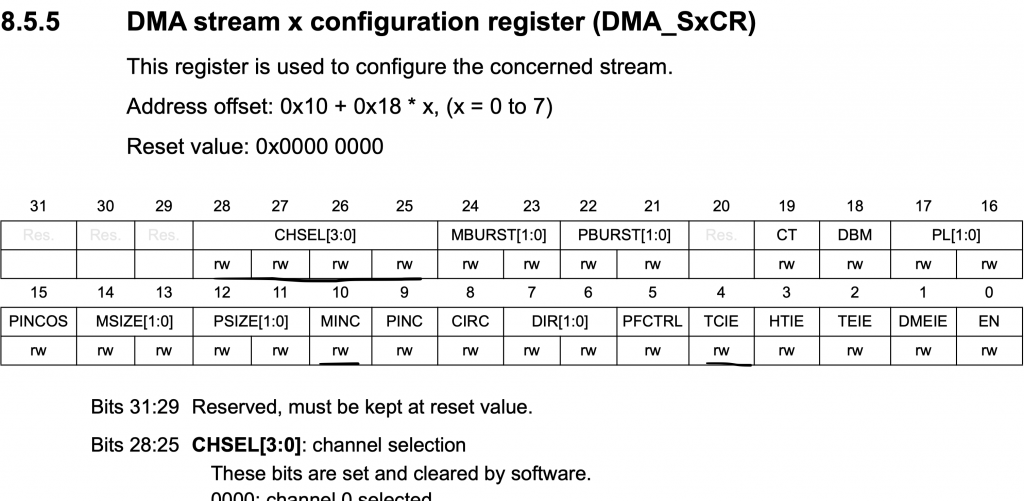
#define CH1	0x01
DMA1_Stream5->CR|=(CH1<<25)|DMA_SxCR_MINC|DMA_SxCR_TCIE;
Enable DMA1_Stream5 interrupt in NVIC:
NVIC_EnableIRQ(DMA1_Stream5_IRQn);
Set the peripheral address to be the RXDR:
DMA1_Stream5->PAR=(uint32_t )&I2C1->RXDR;
2. I2C Read using DMA:
We start of by declaring a function that takes four arguments:
- Slave address
- Memory address.
- Buffer to store the read data.
- Length of data to be read.
void i2c_read_dma(uint8_t slav_add, uint8_t memadd, uint8_t *data, uint8_t length)
For the sending memory address, it is the same part from the previous guide:
		/*Enable I2C*/
		I2C1->CR1 |=I2C_CR1_PE;
		/*Disable DMA for short period of time*/
		/*Set slave address*/
		I2C1->CR2=(slav_add<<1);
		/*7-bit addressing*/
		I2C1->CR2&=~I2C_CR2_ADD10;
		/*Set number to transfer to 1 for write operation*/
		I2C1->CR2|=(1<<I2C_CR2_NBYTES_Pos);
		/*Set the mode to write mode*/
		I2C1->CR2&=~I2C_CR2_RD_WRN;
		/*Software end*/
		I2C1->CR2&=~I2C_CR2_AUTOEND;
		/*Generate start*/
		I2C1->CR2|=I2C_CR2_START;
		/*Wait until transfer is completed*/
		while(!(I2C1->ISR & I2C_ISR_TC))
			{
				/*Check if TX buffer is empty*/
				if(I2C1->ISR & I2C_ISR_TXE)
					{
						/*send memory address*/
						I2C1->TXDR = (memadd);
					}
			}
	/*Reset I2C*/
	I2C1->CR1 &=~I2C_CR1_PE;
	I2C1->CR1 |=I2C_CR1_PE;
In the CR1 register of I2C, enable RXDMA bit:
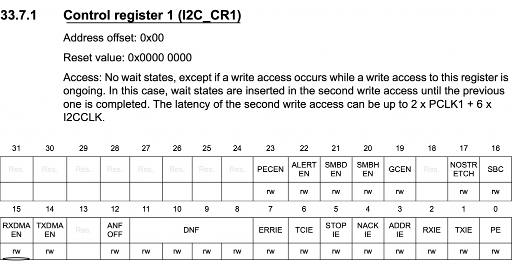
	/*Enable DMA TX*/
	I2C1->CR1|=I2C_CR1_RXDMAEN;
Set the slave address:
	/*Set slave address*/
	I2C1->CR2=(slav_add<<1);
Set the mode to be read mode:
	/*Set mode to read operation*/
	I2C1->CR2|=I2C_CR2_RD_WRN;
Set the length of the data to be read:
	/*Set length to the required length*/
	I2C1->CR2|=((length)<<I2C_CR2_NBYTES_Pos);
Enable autoend:
	/*auto generate stop after transfer completed*/
	I2C1->CR2|=I2C_CR2_AUTOEND;
Now, for the DMA part, set the memory address to be the buffer passed by the user:
DMA1_Stream5->M0AR=(uint32_t)data;
Set transfer length:
DMA1_Stream5->NDTR=length;
Finally enable the stream:
DMA1_Stream5->CR |=DMA_SxCR_EN;
Launch I2C:
I2C1->CR2|=I2C_CR2_START;
Wait until the transfer is completed:
	while(rx_finished==0);
	rx_finished=0;
For interrupt handler:
void DMA1_Stream5_IRQHandler(void)
	{
		if(DMA1->HISR & DMA_HISR_TCIF5){
		rx_finished=1;
		DMA1->HIFCR=DMA_HIFCR_CTCIF5;
		}

	}
Hence, the codes as following:
#include "i2c_dma.h"

#include "stm32f7xx.h"


volatile uint8_t rx_finished;

void i2c_dma_init(uint32_t timing)
	{
		#define AF4 0x04
		#define CH1	0x01
		RCC->AHB1ENR|=RCC_AHB1ENR_GPIOBEN;
		GPIOB->MODER|=GPIO_MODER_MODER8_1|GPIO_MODER_MODER9_1;
		GPIOB->MODER&=~(GPIO_MODER_MODER8_0|GPIO_MODER_MODER9_0);
		GPIOB->OTYPER|=GPIO_OTYPER_OT8|GPIO_OTYPER_OT9;
		GPIOB->AFR[1]|=(AF4<<0)|(AF4<<4);

		RCC->APB1ENR|=RCC_APB1ENR_I2C1EN;

		I2C1->CR1 &=~I2C_CR1_PE;
		/*Enable I2C*/
		I2C1->TIMINGR=timing;
		I2C1->CR1 |=I2C_CR1_PE;

		/*Configuring DMA1_Stream5*/
		RCC->AHB1ENR|=RCC_AHB1ENR_DMA1EN;
		DMA1_Stream5->CR &=~DMA_SxCR_EN;
		while((DMA1_Stream5->CR & DMA_SxCR_EN)==1);
		DMA1_Stream5->CR|=(CH1<<25)|DMA_SxCR_MINC|DMA_SxCR_TCIE;
		NVIC_EnableIRQ(DMA1_Stream5_IRQn);
		DMA1_Stream5->PAR=(uint32_t )&I2C1->RXDR;
	}


void i2c_read_dma(uint8_t slav_add, uint8_t memadd, uint8_t *data, uint8_t length)
	{

		/*Enable I2C*/
		I2C1->CR1 |=I2C_CR1_PE;
		/*Disable DMA for short period of time*/
		/*Set slave address*/
		I2C1->CR2=(slav_add<<1);
		/*7-bit addressing*/
		I2C1->CR2&=~I2C_CR2_ADD10;
		/*Set number to transfer to 1 for write operation*/
		I2C1->CR2|=(1<<I2C_CR2_NBYTES_Pos);
		/*Set the mode to write mode*/
		I2C1->CR2&=~I2C_CR2_RD_WRN;
		/*Software end*/
		I2C1->CR2&=~I2C_CR2_AUTOEND;
		/*Generate start*/
		I2C1->CR2|=I2C_CR2_START;
		/*Wait until transfer is completed*/
		while(!(I2C1->ISR & I2C_ISR_TC))
			{
				/*Check if TX buffer is empty*/
				if(I2C1->ISR & I2C_ISR_TXE)
					{
						/*send memory address*/
						I2C1->TXDR = (memadd);
					}
			}
	/*Reset I2C*/
	I2C1->CR1 &=~I2C_CR1_PE;
	I2C1->CR1 |=I2C_CR1_PE;
	/*Enable DMA TX*/
	I2C1->CR1|=I2C_CR1_RXDMAEN;
	/*Set slave address*/
	I2C1->CR2=(slav_add<<1);
	/*Set mode to read operation*/
	I2C1->CR2|=I2C_CR2_RD_WRN;
	/*Set length to the required length*/
	I2C1->CR2|=((length)<<I2C_CR2_NBYTES_Pos);
	/*auto generate stop after transfer completed*/
	I2C1->CR2|=I2C_CR2_AUTOEND;
	DMA1_Stream5->M0AR=(uint32_t)data;
	DMA1_Stream5->NDTR=length;
	DMA1_Stream5->CR |=DMA_SxCR_EN;
	/*Generate start*/
	I2C1->CR2|=I2C_CR2_START;
	while(rx_finished==0);
	rx_finished=0;
	}


void DMA1_Stream5_IRQHandler(void)
	{
		if(DMA1->HISR & DMA_HISR_TCIF5){
		rx_finished=1;
		DMA1->HIFCR=DMA_HIFCR_CTCIF5;
		}

	}
For the header file:
#ifndef I2C_DMA_H_
#define I2C_DMA_H_


#include "stdint.h"


void i2c_dma_init(uint32_t timing);
void i2c_read_dma(uint8_t slav_add, uint8_t memadd, uint8_t *data, uint8_t length);


#endif /* I2C_DMA_H_ */
3. Code:
In main.c file:
#include "uart.h"
#include "i2c_dma.h"
#include "stdlib.h"
#include "stm32f7xx.h"
#define slave_add (0x68)
uint8_t data_rec[3];
uint8_t data_send[4];


void delay(int ms)
{
	int i;
	SysTick->LOAD=16000-1;
	SysTick->VAL=0;
	SysTick->CTRL=0x5;
		for ( i=0;i<ms;i++)
		{
			while(!(SysTick->CTRL &0x10000)){}
		}
	SysTick->CTRL=0;

}


int bcd_to_decimal(unsigned char x) {
    return x - 6 * (x >> 4);
}


int main(void)
	{

		uart3_tx_init();
		i2c_dma_init(0x00303D5B);

		printf("init\r\n");
		while(1)
			{
				i2c_read_dma(slave_add,0x00,data_rec,3);
				for (volatile int i=0;i<3;i++)
					{
						data_rec[i]=bcd_to_decimal(data_rec[i]);
					}
				if(data_rec[0]!=0){
				if(data_rec[0]%5==0){
						data_send[0]=0x00;
						data_send[1]=0x00;
						data_send[2]=(rand() % 5);
						data_send[3]=(rand() % 5);
						i2c_write_dma(slave_add,data_send,4);
						}}
				printf("rtc data %d %d %d\r\n",data_rec[0],data_rec[1],data_rec[2]);
				delay(100);


			}


	}
4. Results:
If you run the code and open terminal application and set baudrate to 115200, you should get the following:
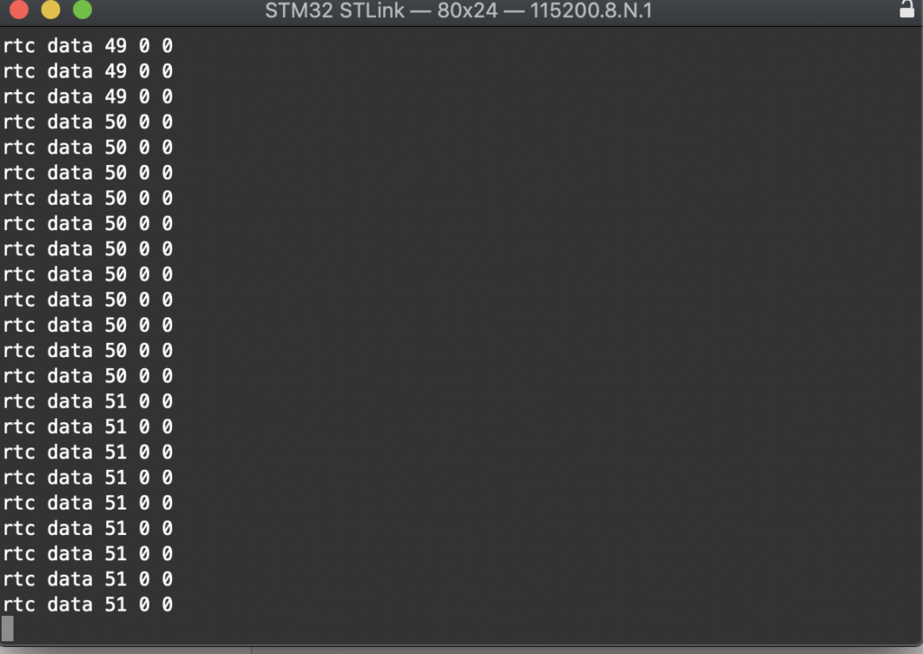
From left to right:
- Seconds.
- Minutes.
- Hours.
Happy coding 🙂
Add Comment