In this guide, we shall see how to push STM32L053 to run at 32MHz rather than the default frequency of 2.096 MHz.
1. Steps:
In order to push STM32L053 to maximum, we shall use external oscillator. Since the Nucleo-L053 has built-in 8Mhz generated from ST-Link, we shall use that as our oscillator.
The steps are as following:
- Set flash latency to 1WS (waiting cycle).
- Bypass the HSE oscillator.
- Enable HSE.
- Disable the PLL.
- Configure the PLL.
- Enable the PLL.
- Select the PLL as the clock source.
2. Coding:
Create a new source and header file with name of core.c and core.h
Inside core.c, create a function:
void config_core_32mhz()
{
}
Inside the function:
Set flash latency to 1WS and wait for the value to set:
	FLASH->ACR |= FLASH_ACR_LATENCY; /* (1) */
	while (!(FLASH->ACR & FLASH_ACR_LATENCY));
Bypass the HSE:
RCC->CR|=RCC_CR_HSEBYP;
Enable the HSE and wait for the HSE to be ready:
	RCC->CR|=RCC_CR_HSEON;
	while(!(RCC->CR & RCC_CR_HSERDY));
Disable the PLL and wait for the PLL to be disabled:
	RCC->CR &= ~RCC_CR_PLLON; /* (3) */
	while ((RCC->CR & RCC_CR_PLLRDY));
Set the PLL multiplication to 8, divider to 2 and source to be HSE:
	RCC->CFGR |= RCC_CFGR_PLLMUL8;
	RCC->CFGR |= RCC_CFGR_PLLDIV2;
	RCC->CFGR |= RCC_CFGR_PLLSRC_HSE;
Enable the PLL and wait until the PLL is ready:
	RCC->CR |= RCC_CR_PLLON;
	while (!(RCC->CR & RCC_CR_PLLRDY));
Switch to PLL to be the source:
	RCC->CFGR |= RCC_CFGR_SW_PLL;
	while (!(RCC->CFGR & RCC_CFGR_SWS_PLL) );
Thats it for the source file.
For the header:
#ifndef CORE_H_
#define CORE_H_
void config_core_32mhz();


#endif /* CORE_H_ */
3. Testing Using Systick:
In main.c:
#include "delay.h"
#include "stm32l0xx.h"
extern void config_core_32mhz();
int main(void)
{
	config_core_32mhz();
	__disable_irq();
	SysTick->LOAD=32000-1;
	SysTick->VAL=0;
	SysTick->CTRL=7;
	__enable_irq();
	RCC->IOPENR |=RCC_IOPENR_IOPAEN;
	GPIOA->MODER|= GPIO_MODER_MODE5_0; //PA5 as output
	GPIOA->MODER&=~ GPIO_MODER_MODE5_1; //PA5 as output

	while(1)
	{

	}

}


void SysTick_Handler(void)
{
GPIOA->ODR^=GPIO_ODR_OD5;

}
Compile and upload the code to your mcu and using oscilloscope and probe PA5 and you should get the following:
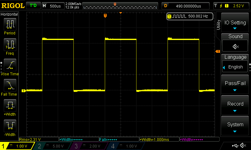
Since each division of the horizontal line is 500microseconds, and we are getting 2 division high and two division low, thats mean the on time 1 millisecond and 1 millisecond off which as we set it. Thats mean we successfully changed the core frequency from 2.096MHz to 32MHz. Now, you can get the full potential of your mcu.
Happy coding 🙂
Add Comment