
In the previous guide, we took a look at the NEC IR protocol and setup STM32 to run at 64MHz. In this guide, we shall setup some required peripheral.
In this guide, we shall cover the following:
- Hardware setup.
- I2C and OLED setup.
- Output Compare Interrupt.
- External Interrupt.
3. Hardware Setup:
The following parts are required:
- VS1838B which is IR Receiver and can modulate a carrier frequency of 38KHz.
- I2C OLED Display
- STM32F407 Discovery (or any stm32f4 will work).
The connection as following:
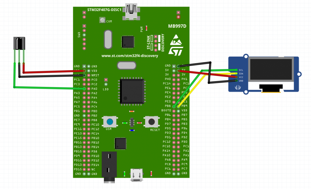
The data of the IR Receiver connected to PA1.
For the OLED display:
| STM32F407 | SSD1306 OLED |
|---|---|
| PB8 /I 2C1 | SCL |
| PB9 / I2C1 | SDA |
| 5V | Vcc |
| GND | GND |
4. I2C and OLED Code:
You can download the OLED with I2C from here.
However, the I2C code for 100MHz and in this case, the core frequency is 64MHz. Hence, the initialization of I2C is as following:
uint8_t inited=0;
void i2c_init(void){
if(inited==0){
RCC->AHB1ENR|=RCC_AHB1ENR_GPIOBEN; //enable gpiob clock
RCC->APB1ENR|=RCC_APB1ENR_I2C1EN; //enable i2c1 clock
GPIOB->MODER|=0xA0000; //set pb8and9 to alternative function
GPIOB->AFR[1]|=0x44;
GPIOB->OTYPER|=GPIO_OTYPER_OT8|GPIO_OTYPER_OT9; //set pb8 and pb9 as open drain
I2C1->CR1=I2C_CR1_SWRST;
I2C1->CR1&=~I2C_CR1_SWRST;
I2C1->CR2|=0x20;
I2C1->CCR|=0x801b;
I2C1->TRISE=0xa; //output max rise
I2C1->CR1|=I2C_CR1_PE;
inited=1;
}
}
5. Output Comare Interrupt:
Since it is required to set the timer to have 10uS resolution, the prescaler shall be 640 and the ARR is 0xFFFF as following:
static void TIM2_init()
	{
		RCC->APB1ENR|=RCC_APB1ENR_TIM2EN;
		TIM2->PSC=PRESCALER_10_US;
		TIM2->ARR=0xFFFF;
		TIM2->DIER=TIM_DIER_CC1IE;
		TIM2->CCR1=TIME_120_MS;
		TIM2->CR1 |= TIM_CR1_ARPE;
		TIM2->EGR|=TIM_EGR_CC1G;


		//TIM2->CCMR1|=TIM_CCMR1_OC1M_0|TIM_CCMR1_OC1M_1;
		TIM2->CCER |= TIM_CCER_CC1E;
		TIM2->SR =0;
		NVIC_EnableIRQ(TIM2_IRQn);

	}
For the interrupt handler:
 void TIM2_IRQHandler(void)
	{

		if(TIM2->SR & TIM_SR_CC1IF){ /*Interrupt from CC1*/
		TIM2->SR =0; /*Clear pending interrupt*/

	}

	}
6. External Interrupt:
Since the data output of the IR receiver is connected to PA1, we need to set it as interrupt with internal pullup resistor:
static void GPIO_init()
	{

	RCC->AHB1ENR|=RCC_AHB1ENR_GPIOAEN;
	RCC->APB2ENR |=RCC_APB2ENR_SYSCFGEN;

	GPIOA->MODER&=~GPIO_MODER_MODE1;
	GPIOA->PUPDR|=GPIO_PUPDR_PUPD1_0;

	SYSCFG->EXTICR[0]|=SYSCFG_EXTICR1_EXTI1_PA;
	EXTI->IMR|=EXTI_IMR_IM1;
	EXTI->RTSR |=EXTI_RTSR_TR1;
	EXTI->FTSR |=EXTI_FTSR_TR1;
	NVIC_EnableIRQ(EXTI1_IRQn);

	}
Interrupt handler:
void EXTI1_IRQHandler(void)
	{
	EXTI->PR |=EXTI_PR_PR1; /*Clear pending interrupt*/

	}
7. Code:
You may download the code from here:
Contains:
- Set the frequency to 64MHz.
- I2C and OLED.
- Output Compare interrupt.
- External interrupt.
In next part, we shall see how to develop the code required to decode the NEC protocol.
Add Comment