In this guide series, we shall see how NEC protocol works and how to decode the commands from NEC enabled IR Remote.
In this part of the guide, we shall cover the following:
- NEC Protocol
- STM32F4 Core settings to 64MHz.
1. NEC Protocol:
The NEC IR transmission protocol uses pulse distance encoding of the message bits. Each pulse burst (mark – RC transmitter ON) is 562.5µs in length, at a carrier frequency of 38kHz (26.3µs). Logical bits are transmitted as follows:
- Logical ‘0’ – a 562.5µs pulse burst followed by a 562.5µs space, with a total transmit time of 1.125ms
- Logical ‘1’ – a 562.5µs pulse burst followed by a 1.6875ms space, with a total transmit time of 2.25ms
Features
- 8 bit address and 8 bit command length.
- Extended mode available, doubling the address size.
- Address and command are transmitted twice for reliability.
- Pulse distance modulation.
- Carrier frequency of 38kHz.
- Bit time of 1.125ms or 2.25ms.
Modulation

The NEC protocol uses pulse distance encoding of the bits. Each pulse is a 560µs long 38kHz carrier burst (about 21 cycles). A logical “1” takes 2.25ms to transmit, while a logical “0” is only half of that, being 1.125ms. The recommended carrier duty-cycle is 1/4 or 1/3.
Protocol

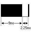
The picture above shows a typical pulse train of the NEC protocol. With this protocol the LSB is transmitted first. In this case Address $59 and Command $16 is transmitted. A message is started by a 9ms AGC burst, which was used to set the gain of the earlier IR receivers. This AGC burst is then followed by a 4.5ms space, which is then followed by the Address and Command. Address and Command are transmitted twice. The second time all bits are inverted and can be used for verification of the received message. The total transmission time is constant because every bit is repeated with its inverted length. If you’re not interested in this reliability you can ignore the inverted values, or you can expand the Address and Command to 16 bits each!
Keep in mind that one extra 560µs burst has to follow at the end of the message in order to be able to determine the value of the last bit.

A command is transmitted only once, even when the key on the remote control remains pressed. Every 110ms a repeat code is transmitted for as long as the key remains down. This repeat code is simply a 9ms AGC pulse followed by a 2.25ms space and a 560µs burst.

Extended NEC protocol
The NEC protocol is so widely used that soon all possible addresses were used up. By sacrificing the address redundancy the address range was extended from 256 possible values to approximately 65000 different values. This way the address range was extended from 8 bits to 16 bits without changing any other property of the protocol.
By extending the address range this way the total message time is no longer constant. It now depends on the total number of 1’s and 0’s in the message. If you want to keep the total message time constant you’ll have to make sure the number 1’s in the address field is 8 (it automatically means that the number of 0’s is also 8). This will reduce the maximum number of different addresses to just about 13000.
The command redundancy is still preserved. Therefore each address can still handle 256 different commands.

Keep in mind that 256 address values of the extended protocol are invalid because they are in fact normal NEC protocol addresses. Whenever the low byte is the exact inverse of the high byte it is not a valid extended address.
2. Setting STM32F4 to 64MHz:
For detailed method of configuring the clock to desired frequency (100MHz in this case), check the following topic (here).
For setting STM32F407 to 64MHz, the following code is used :
void SysClockConfig(void) //set the core frequency to 100MHz
{
#define PLL_M      4
#define PLL_N      64
#define PLL_P      2
#define PLL_Q      4

__IO uint32_t StartUpCounter = 0, HSEStatus = 0;


  RCC->CR |= ((uint32_t)RCC_CR_HSEON);


  do
  {
    HSEStatus = RCC->CR & RCC_CR_HSERDY;
    StartUpCounter++;
  } while((HSEStatus == 0) && (StartUpCounter != 3000));

  if ((RCC->CR & RCC_CR_HSERDY) != RESET)
  {
    HSEStatus = (uint32_t)0x01;
  }
  else
  {
    HSEStatus = (uint32_t)0x00;
  }

  if (HSEStatus == (uint32_t)0x01)
  {

    RCC->APB1ENR |= RCC_APB1ENR_PWREN;
    PWR->CR &= (uint32_t)~(PWR_CR_VOS);


    RCC->CFGR |= RCC_CFGR_HPRE_DIV1;


    RCC->CFGR |= RCC_CFGR_PPRE2_DIV1;


    RCC->CFGR |= RCC_CFGR_PPRE1_DIV2;


    RCC->PLLCFGR = PLL_M | (PLL_N << 6) | (((PLL_P >> 1) -1) << 16) |
                   (RCC_PLLCFGR_PLLSRC_HSE) | (PLL_Q << 24);


    RCC->CR |= RCC_CR_PLLON;


    while((RCC->CR & RCC_CR_PLLRDY) == 0)
    {
    }

    /* Configure Flash prefetch, Instruction cache, Data cache and wait state */
    FLASH->ACR = FLASH_ACR_ICEN |FLASH_ACR_DCEN |FLASH_ACR_LATENCY_3WS;

    /* Select the main PLL as system clock source */
    RCC->CFGR &= (uint32_t)((uint32_t)~(RCC_CFGR_SW));
    RCC->CFGR |= RCC_CFGR_SW_PLL;

    /* Wait till the main PLL is used as system clock source */
    while ((RCC->CFGR & (uint32_t)RCC_CFGR_SWS ) != RCC_CFGR_SWS_PLL)
    {;}
  }
  else
  { /* If HSE fails to start-up, the application will have wrong clock
         configuration. User can add here some code to deal with this error */
  }

}
In next part, we shall implement the firmware of the NEC decoder.
Happy coding 🙂
Add Comment