


In the previous guide (here), we saw how to configure a GPIO pin as output. In this guide, we shall configure another pin an input to read from push button.
In this guide, will cover the following:
- Input modes.
- Develop GPIO Input driver.
- LED control using push button.
- Demo.
1. Input modes:
GPIO input modes include
- high impedance
- pull-up
- pull-down
Floating, High Impedance, Tri-Stated
Floating, high impedance, and tri-stated are three terms that mean the same thing: the pin is just flopping in the breeze. Its state is indeterminate unless it is driven high or low externally. You only want to configure a pin as floating if you know it will be driven externally. Otherwise, configure the input using pulling resistors.
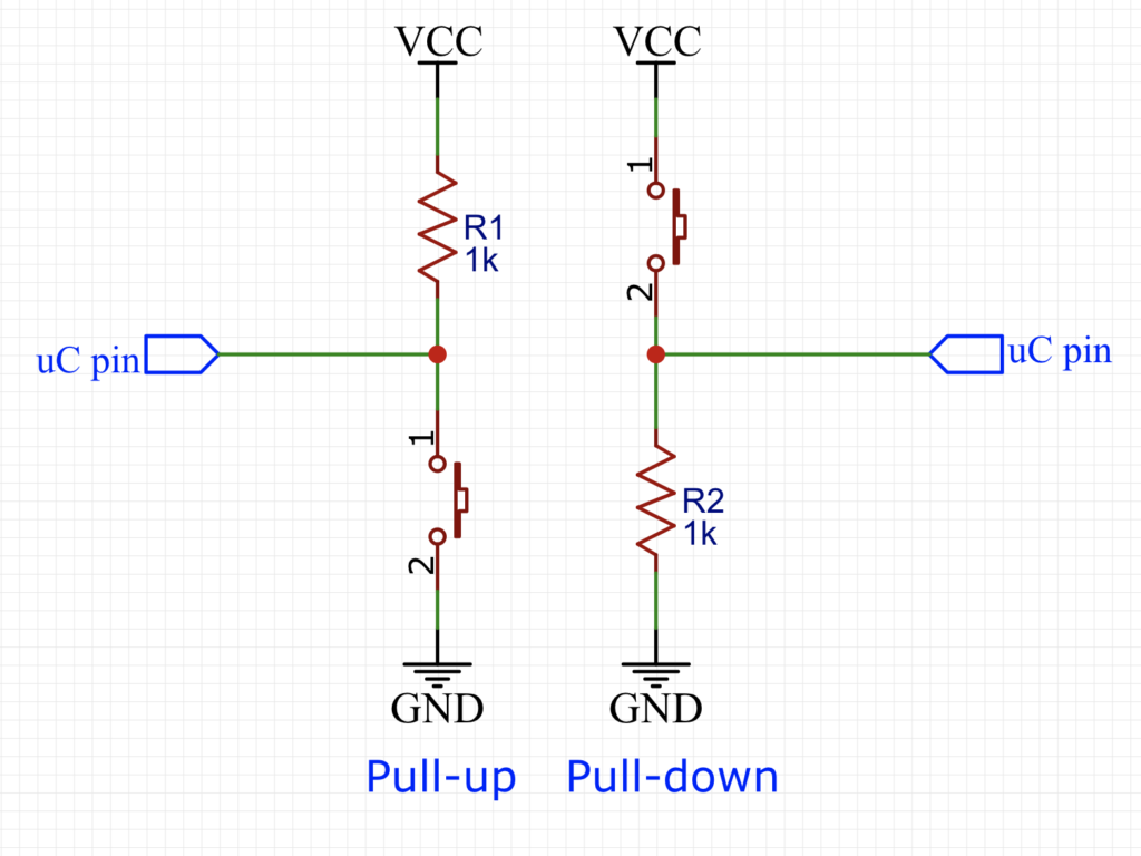
Pull Up/Down
If an input is configured with an internal pull-up, it will be high unless it is externally driven low. Pull-down inputs do the opposite ( they’re low unless driven high).
2. Developing GPIO Input Driver:
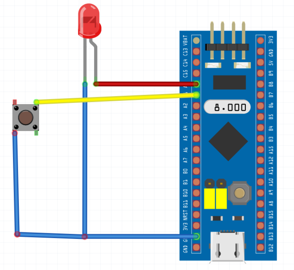
In this guide, the push button is connected to PA1 and LED to PA0 as following:
In order to configure PA1 to input mode the following shall be set:
- Mode to be input mode.
- Configuration to be Input with pull-up / pull-down.
- Enable pull-up resistor.
To set the pin to input mode, the mode shall be set to 0 and configuration to be input with pull-up / pull-down:
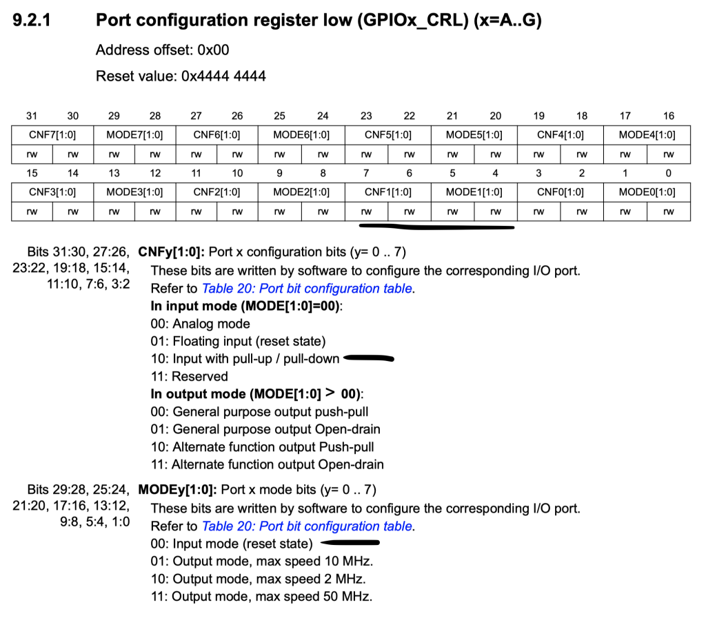
GPIOA->CRL&=~GPIO_CRL_MODE1;
GPIOA->CRL|=GPIO_CRL_CNF1_1;
GPIOA->CRL&=~GPIO_CRL_CNF1_0;
In order to activate pull-up or pull down resistor within the GPIO, the ODR register shall be set as following:
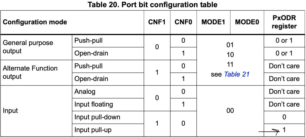
- ODR1 set to 0 means pull-down.
- ODR1 set to 1 means pull-up.
Hence, by setting ODR1 to 1, the internal pull-up will be activated:
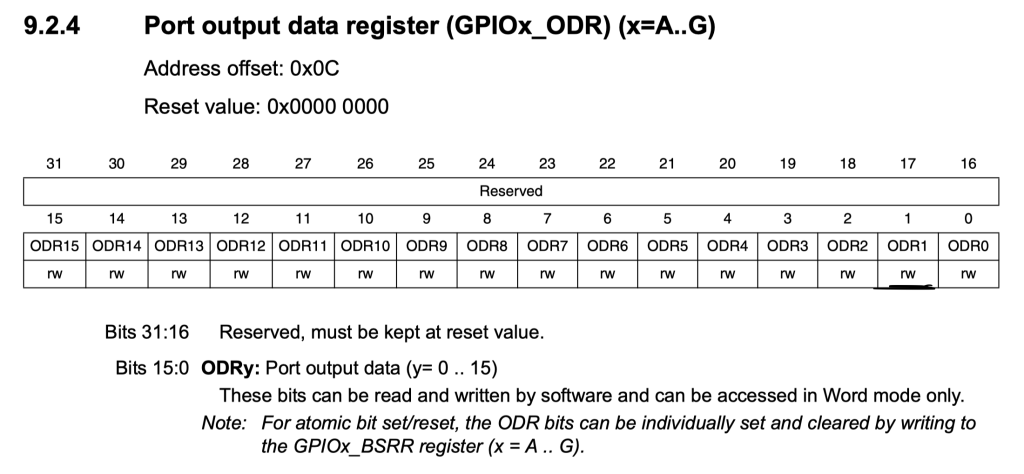
GPIOA->ODR|=GPIO_ODR_ODR1;
Related course
Continue with STM32 peripheral drivers
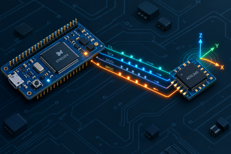
To build on this example, the course uses STM32F4 to develop GPIO, UART, ADC, timers, interrupts, I2C and SPI drivers. Its ADXL345 examples connect peripheral configuration to sensor data. It provides transferable foundations; other devices and STM32 families require their own register and hardware checks.
3. LED control using push-button:
The control algorithm when the push button is pressed, turn on the LED, when released, turn off the LED.
Since the push-button configuration is pull-up, when the push-button is pressed, the respective bit is 0 and when released, the bit is 1.
To read the push-button, we need to read IDR register and bit named IDR1:
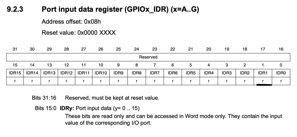
Hence, the code for controlling the LED:
		if((GPIOA->IDR&GPIO_IDR_IDR1)==0){
		GPIOA->BSRR=GPIO_BSRR_BS0;}
		else {
		GPIOA->BSRR=GPIO_BSRR_BR0;}
Hence, the entire code as following:
#include "stm32f1xx.h"


int main(void)
{
	RCC->APB2ENR|=RCC_APB2ENR_IOPAEN;

	/*Configure PA0 as output*/
	GPIOA->CRL|=GPIO_CRL_MODE0;
	GPIOA->CRL&=~(GPIO_CRL_CNF0);

	/*Configure PA1 as input*/

	GPIOA->CRL&=~GPIO_CRL_MODE1;
	GPIOA->CRL|=GPIO_CRL_CNF1_1;
	GPIOA->CRL&=~GPIO_CRL_CNF1_0;
	GPIOA->ODR|=GPIO_ODR_ODR1;


	while(1)
	{
		if((GPIOA->IDR&GPIO_IDR_IDR1)==0){
		GPIOA->BSRR=GPIO_BSRR_BS0;}
		else {
		GPIOA->BSRR=GPIO_BSRR_BR0;}

	}
}
4. Demo:
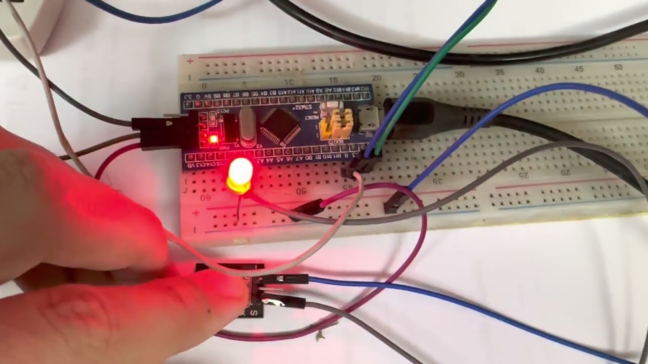
LED control using push button with STM32
Hosted by YouTube. Playing may use YouTube cookies. Privacy details
Happy coding 🙂
Discussion