


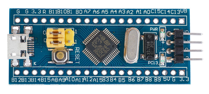
In this new guide series, we shall develop some drivers for the most widely used STM32 which STM32F103 aka bluepill.
In this guide, we shall cover the following:
- Setting up the environment
- Getting the required documents.
- Developing GPIO output driver.
- Code.
- Demo.
1. Setting up the environment:
To setup the environment, please refer to the following topic here.
Just modify it for STM32F103.
For the symbols, use the following:
STM32F103xB
2. Getting the required documents:
First document needed is the datasheet.
You can get the datasheet from here.
Also, you need the reference manual from here.
3. Developing GPIO Output Driver:
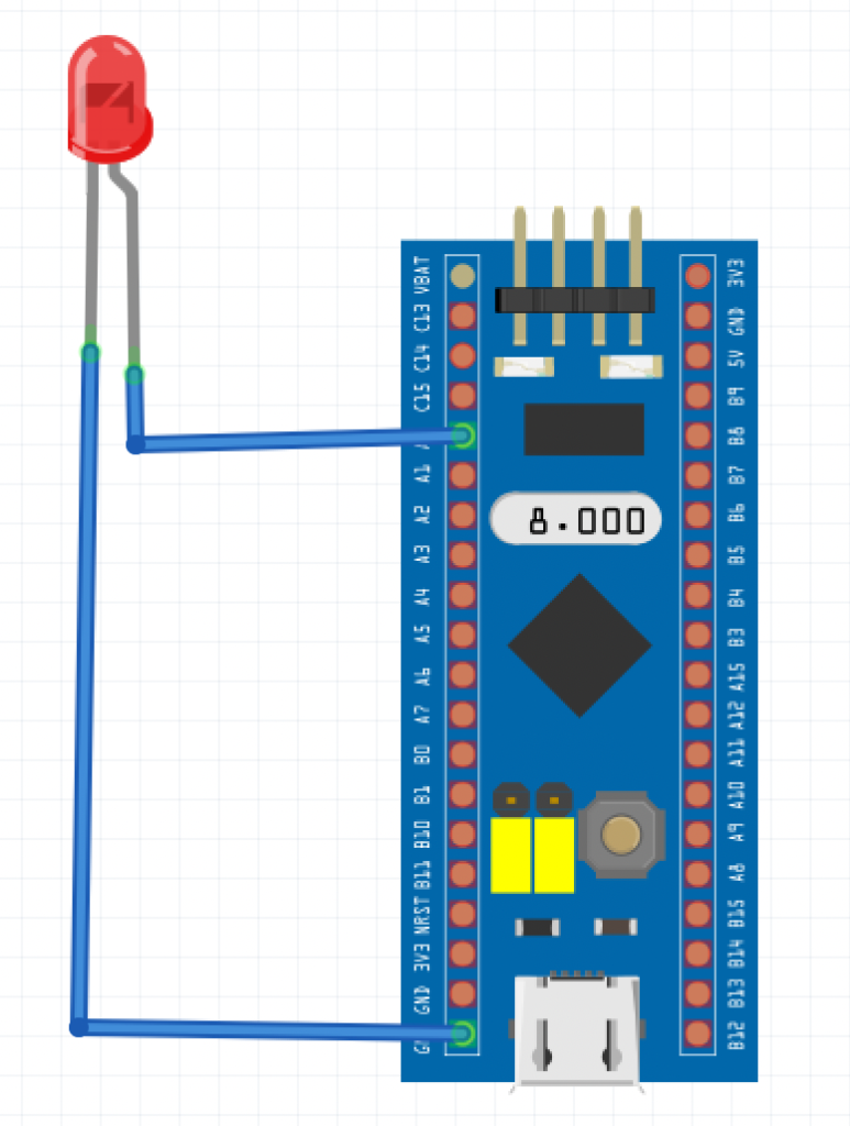
Since the guide uses external LED, we shall use GPIOA pin 0 to blink the LED. The connection the LED to STM32F103 as following:
Since the LED is connected to Port A, we need to enable clock access to GPIO. From the datasheet, we can find the block diagram:
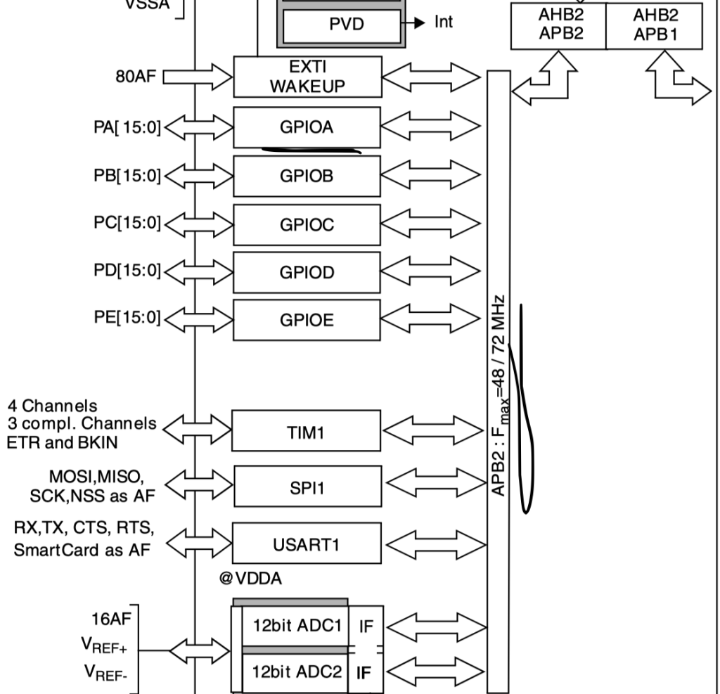
Since GPIOA is connected to APB2 bus, we can enable clock access to GPIOA from RCC_APB2ENR register:
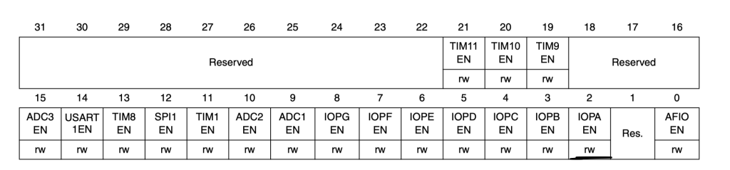
RCC->APB2ENR|=RCC_APB2ENR_IOPAEN;
Then GPIO configuration:
Since the LED is connected to PA0, we need to use Port configuration register low (CRL) which can configure pins from 0 to 7 while Port configuration register high (CRH) configure pins from 8 to 15.
First thing we need the following:
- Configure the pin as Output with maximum speed of 50MHz.
- Set the output mode to be output push-pull.
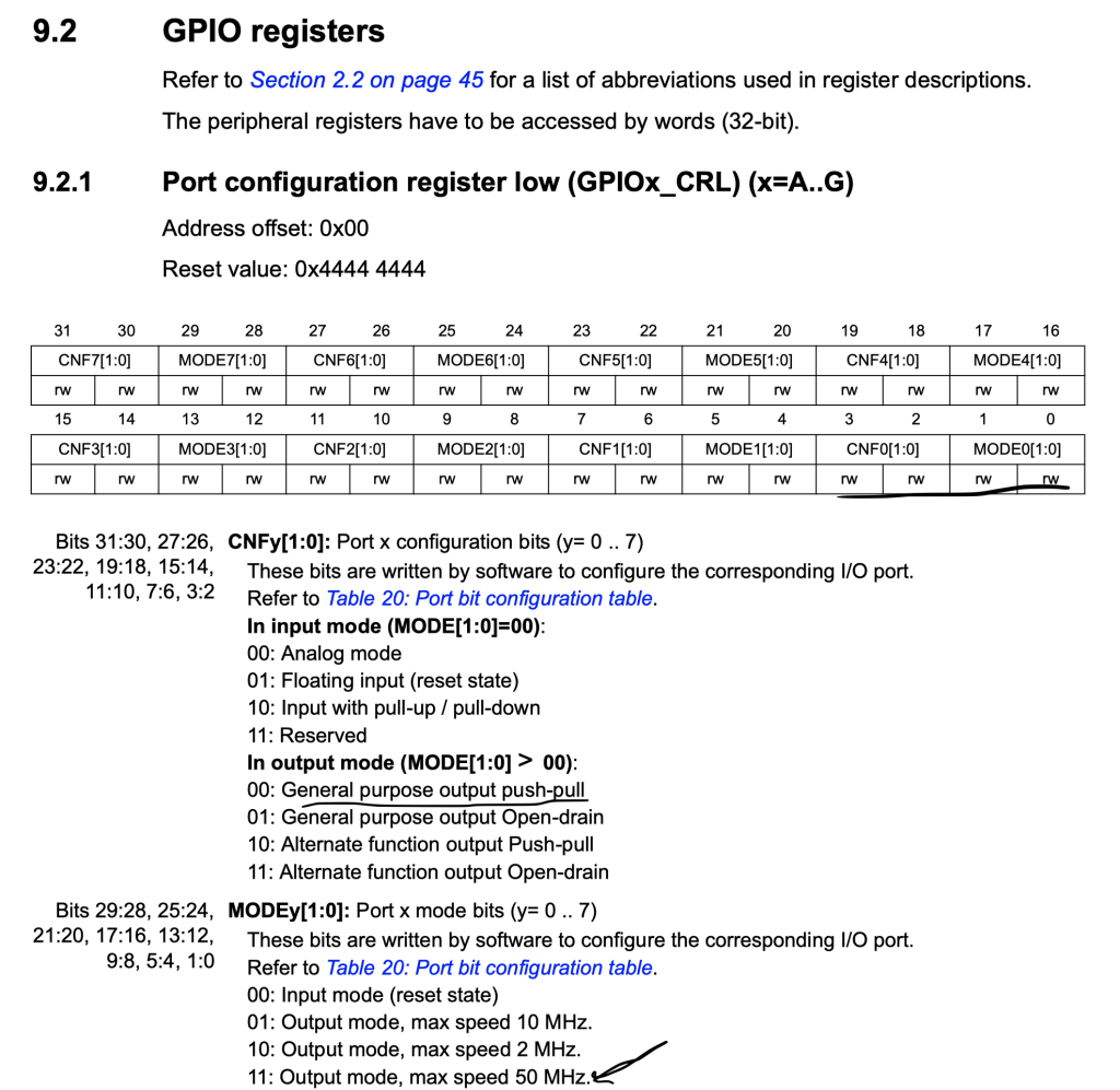
Hence, we need to set bit 0 and 1 to 1 (MODE0) and bit 2 and 3 to 0 (CNF0).
We shall use macros offered by STM32F1 header file
GPIOA->CRL|=GPIO_CRL_MODE0;
	GPIOA->CRL&=~(GPIO_CRL_CNF0);
Then we need to use BSRR register to set and reset the bit:
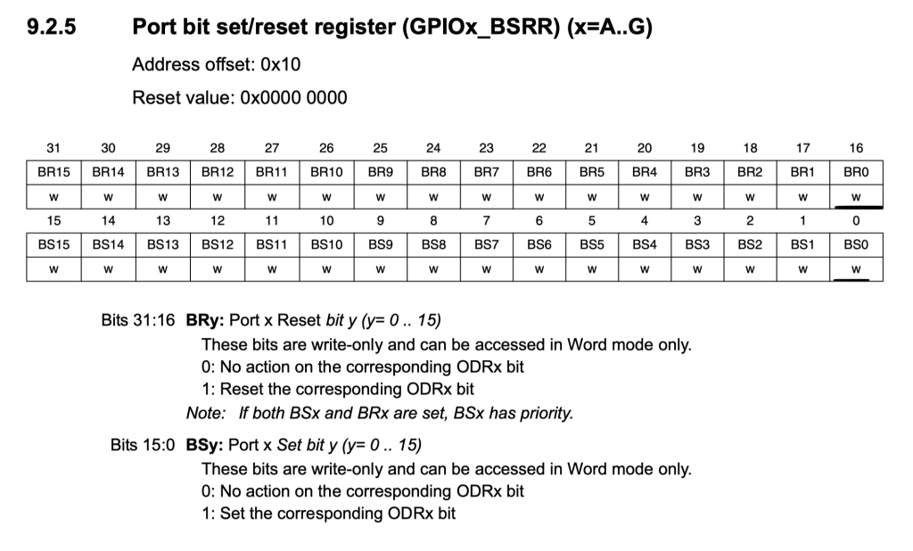
		GPIOA->BSRR=GPIO_BSRR_BS0;
		for(int i=0;i<100000;i++);/*Delay*/
		GPIOA->BSRR=GPIO_BSRR_BR0;
		for(int i=0;i<100000;i++);/*Delay*/
Hence, the code as following:
#include "stm32f1xx.h"


int main(void)
{
	RCC->APB2ENR|=RCC_APB2ENR_IOPAEN;
	GPIOA->CRL|=GPIO_CRL_MODE0;
	GPIOA->CRL&=~(GPIO_CRL_CNF0);

	while(1)
	{
		GPIOA->BSRR=GPIO_BSRR_BS0;
		for(int i=0;i<100000;i++);/*Delay*/
		GPIOA->BSRR=GPIO_BSRR_BR0;
		for(int i=0;i<100000;i++);/*Delay*/


	}
}
Related course
Continue with STM32 peripheral drivers
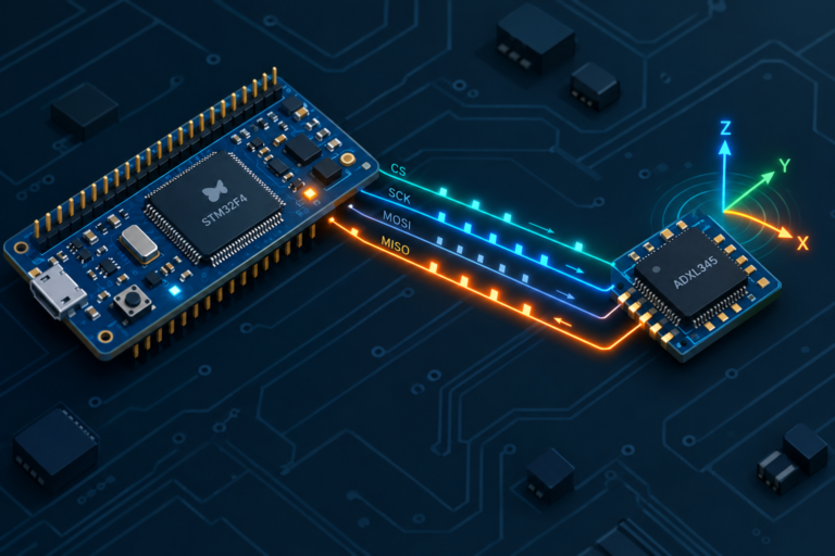
To build on this example, the course uses STM32F4 to develop GPIO, UART, ADC, timers, interrupts, I2C and SPI drivers. Its ADXL345 examples connect peripheral configuration to sensor data. It provides transferable foundations; other devices and STM32 families require their own register and hardware checks.
4. Code:
You may download the code from here:
5. Demo:

Blinking LED on STM32F103
Hosted by YouTube. Playing may use YouTube cookies. Privacy details
Happy coding 🙂
Discussion