
In this guide, we shall investigate how to use timer to generate precise delay in down to microseconds ( will use 500 millisecond) delay here for demonstrations purposes only).
In this guide, we will cover the following:
- What is the timer and how it works
- Configure the timer to generate delay
- Code
- Demo
1 What is the timer and how it works
A Timer Module in its most basic form is a digital logic circuit that counts up every clock cycle. More functionalities are implemented in hardware to support the timer module so it can count up or down. It can have a Prescaler to divide the input clock frequency by a selectable value. It can also have circuitry for input capture, PWM signal generation, and much more as we’ll see in this tutorial.
Let’s consider a basic 16-Bit timer like the one shown below. As a 16-Bit time, it can count from 0 up to 65535. Every clock cycle, the value of the timer is incremented by 1. And as you can see, the Fsys is not the frequency that is incrementing the timer module. But it gets divided by the Prescaler, then it gets fed to the timer.

Basically, in timer mode, the TCNT register is incremented by 1 each clock cycle @ the following frequency (Fsys/PSC). This means if the Fsys is 80MHz & PSC is 1:1024, the TCNT gets incremented by 1 every 12.8μSec. Therefore, if you start this timer to count from 0 until it reaches overflow (at 65535), a flag will be set and starts over from zero
2. Configure the timer to generate delay
We starting by getting to know which timer to use, in this case , we will use TIMER2.
Hence, we need to know which bus is connected to. From the diagram, TIMER2 is connected to APB1 bus.
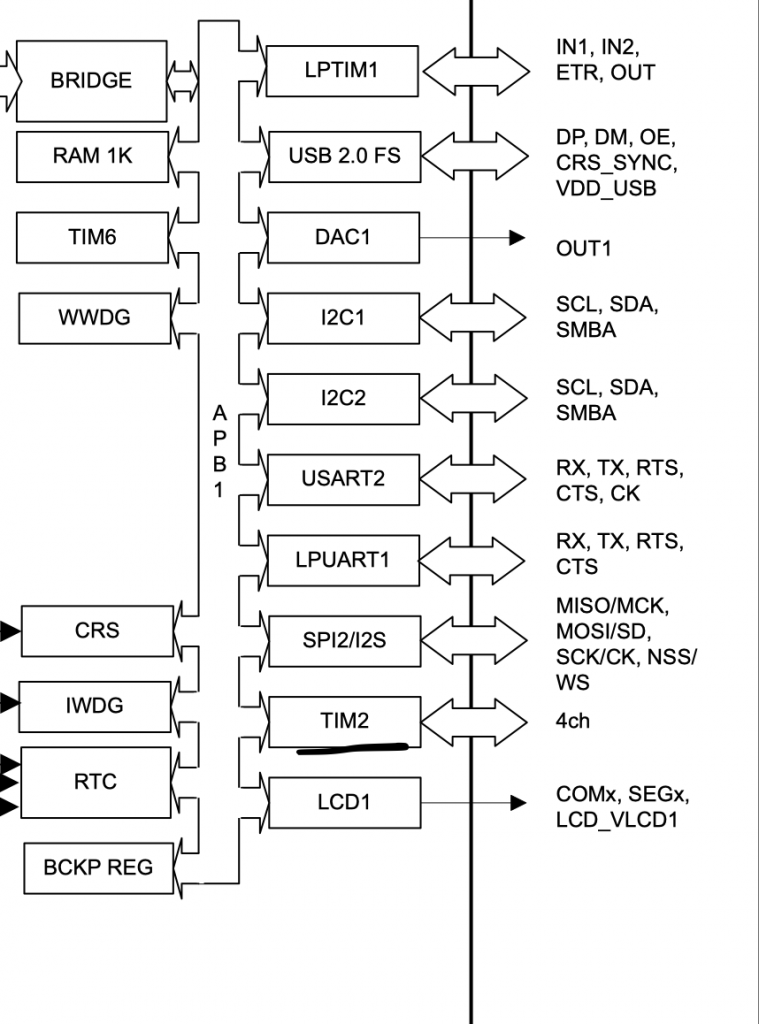
Hence, we can enable clock access to timer2 as following:
- Enabled clock access to TIM2
- Set prescaller to 2097 since STM32l053 is running at 2.09MHz.
void tim2_1ms_init()
	{
	RCC->APB1ENR|=RCC_APB1ENR_TIM2EN;
	TIM2->PSC=2097-1;
	}
Since timer2 is 16-bit, that will be able to generate delay up to 65535 milliseconds which is about 65.5 seconds:
- Set the delay amount in ARR register.
- Reset the counter.
- Start the timer.
- Wait until the timer overflow.
- Disable the timer.
void delay(int ms)
{
if(ms>65535)return;
TIM2->CNT=0;
TIM2->ARR=ms;
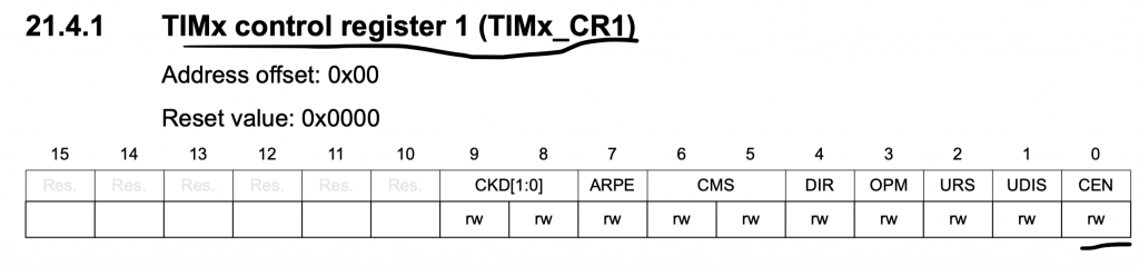
TIM2->CR1|=TIM_CR1_CEN;
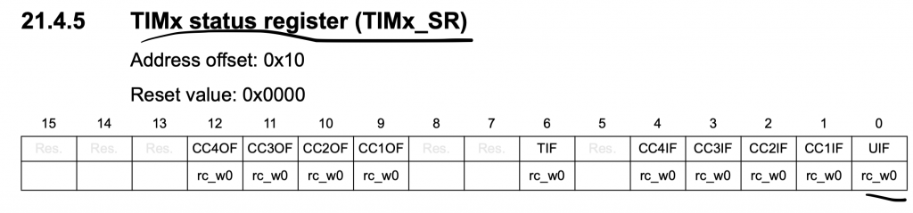
while(!(TIM2->SR & TIM_SR_UIF)){}
TIM2->SR &=~(TIM_SR_UIF);
TIM2->CR1&=~TIM_CR1_CEN;
}
In the main function:
- Set PA5 as output (here).
- Toggle the LED.
- Delay by the amount you need (500ms in this guide).
#include "tim.h"
#include "stm32l0xx.h"
uint32_t adc_data;
int main(void)
{
	/*Enable clock access to GPIOA*/
	RCC->IOPENR |= RCC_IOPENR_GPIOAEN;


	/*Set PA5 as output pin*/
	GPIOA->MODER |= GPIO_MODER_MODE5_0;
	GPIOA->MODER  &=~GPIO_MODER_MODE5_1;
	tim2_1ms_init();
	while(1)
	{
		GPIOA->ODR^=GPIO_ODR_OD5;
		delay(500);

	}

}
3. Code:
You may download the source code from here:
4. Demo:
Happy coding 🙂
Add Comment