
In the previous guide (here), we took a look how to configure the ADC to use DMA with multiple channel. In this guide, we shall use timer to trigger the ADC each 2 second and display the result on serial terminal.
In this guide, we shall cover the following:
- ADC Configuration.
- Timer Configuration.
- DMA Configuration.
- Code.
- Demo.
1. ADC configuration:
The ADC configuration is similar to the ADC in DMA. However, the Continuous mode shall be disabled. Hence, the configuration is similar to the previous guide as following:
	/*Enable clock access to GPIOA and GPIOC*/
	RCC->AHB1ENR|=RCC_AHB1ENR_GPIOAEN|RCC_AHB1ENR_GPIOCEN;
	/*Configure the pins in ADC mode*/
	GPIOA->MODER|=GPIO_MODER_MODER3;
	GPIOC->MODER|=GPIO_MODER_MODER0;

	/*Enable clock access to ADC1*/
	RCC->APB2ENR|=RCC_APB2ENR_ADC1EN;
	/*Enable scan mode*/
	ADC1->CR1|=ADC_CR1_SCAN;
	/*Enable continuous/ DMA and DDS*/
	ADC1->CR2|=ADC_CR2_DDS|ADC_CR2_DMA;
	/*Set length to 2 channels*/
	ADC1->SQR1|=(1<<20);
	/*Set ch3 first first and ch10 second in the conversion sequence*/
	ADC1->SQR3|=(3<<0)|(10<<5);
Note that the continuous mode is disable since the timer shall trigger the ADC conversion not the internal clock of the ADC.
For timer trigger ADC, we shall set the trigger to be rising edge and the source as TIM2 TRGO:
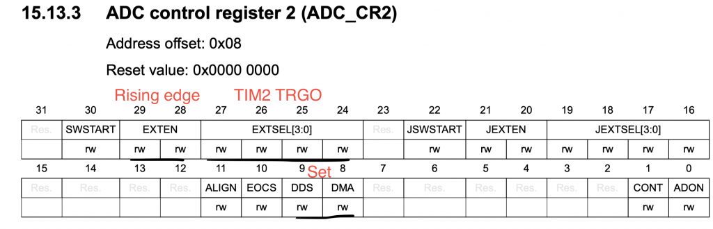
/*Select TIMER2_CH2 as trigger source*/
	ADC1->CR2			|=ADC_CR2_EXTEN_0;
	ADC1->CR2			|=ADC_CR2_EXTSEL_3|ADC_CR2_EXTSEL_1|ADC_CR2_EXTSEL_0;
Note: Don’t enable the ADC (ADON) yet.
2. Timer Configuration:
Since the timer used is Time2, we need to enable clock access to timer2 and set prescaler to 16000-1 and ARR value to 2000-1. Hence those value shall give trigger each second:
	/*Configure the timer*/
	RCC->APB1ENR		|=RCC_APB1ENR_TIM2EN;
	TIM2->PSC			 =16000-1;
	TIM2->ARR			 =2000-1;
Now, we shall set the Master mode selection to Update – The update event is selected as trigger output (TRGO):
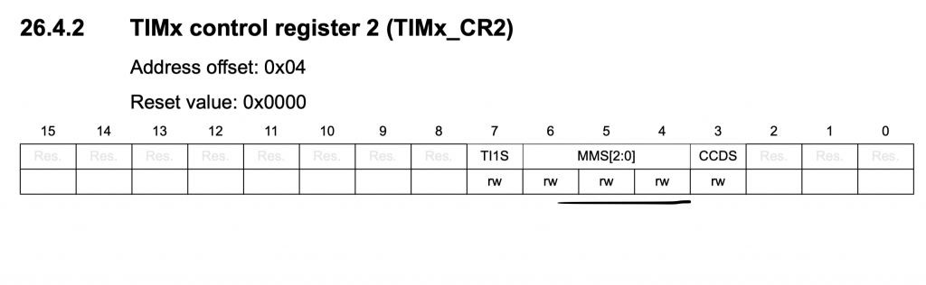
TIM2->CR2 |=TIM_CR2_MMS_1;
3. DMA configuration:
The DMA configuration is similar to part 3 except that there will be interrupt when transfer is completed.
/*Enable clock access to DMA2*/
	RCC->AHB1ENR|=RCC_AHB1ENR_DMA2EN;
	/*Disable the strsam*/
	DMA2_Stream0->CR&=~DMA_SxCR_EN;
	/*Wait until the stream is disabled */
	while(DMA_SxCR_EN==(DMA2_Stream0->CR&DMA_SxCR_EN));
	/*Set memory size to half-word*/
	DMA2_Stream0->CR|=DMA_SxCR_MSIZE_0;
	/*Set peripheral size to half word*/
	DMA2_Stream0->CR|=DMA_SxCR_PSIZE_0;
	/*Enable memory increment*/
	DMA2_Stream0->CR|=DMA_SxCR_MINC;
	/*Enable circular mode*/
	DMA2_Stream0->CR|=DMA_SxCR_CIRC;
	/*Enable Transfer complete interrupt*/
	DMA2_Stream0->CR|=DMA_SxCR_TCIE;
	NVIC_EnableIRQ(DMA2_Stream0_IRQn);
	/*Set number of transfer to 2*/
	DMA2_Stream0->NDTR=2;
	/*Set peripheral address to ADC1->DR*/
	DMA2_Stream0->PAR=(uint32_t)&(ADC1->DR);
	/*Set memory address to adc_data*/
	DMA2_Stream0->M0AR=(uint32_t)&(adc_data);
Finally, enable DMA stream, ADC and timer in this order:
/*Enable the DMA stream*/
	DMA2_Stream0->CR|=DMA_SxCR_EN;
	/*Enable the ADC*/
	ADC1->CR2|=ADC_CR2_ADON;
	/*Start the timer */
	TIM2->CR1			|=TIM_CR1_CEN;
For interrupt handler:
void DMA2_Stream0_IRQHandler(void)
		{

		if(((DMA2->LISR)&DMA_LISR_TCIF0))
				{
				finished=1;
				GPIOB->ODR^=GPIO_ODR_OD7;
				DMA2->LIFCR=DMA_LIFCR_CTCIF0;
				}
		NVIC_ClearPendingIRQ(DMA2_Stream0_IRQn);
		}
For main.c :
#include "stm32f7xx.h"
#include "uart.h"
#include "stdlib.h"
#include "adc_dma.h"
uint16_t data[2];

volatile int finished;
int main()
	{
	 SCB->CPACR |= ((3UL << 10*2)|(3UL << 11*2));
	 RCC->AHB1ENR|=RCC_AHB1ENR_GPIOBEN;
	GPIOB->MODER|=GPIO_MODER_MODER7_0;
	GPIOB->MODER&=~GPIO_MODER_MODER7_1;
	SCB_EnableDCache();
	SCB_EnableICache();
	uart3_tx_init();
	printf("uart is ready\r\n");
	adc_dma_2ch_timer_init();
	while(1)
		{
			if(finished==1)
				{
					finished=0;
					data[0]=ReadChannel(A0);
					data[1]=ReadChannel(A1);
					printf("ADC values A0=%d, A1=%d\r\n",data[0],data[1]);

				}
		}

	}

void DMA2_Stream0_IRQHandler(void)
		{

		if(((DMA2->LISR)&DMA_LISR_TCIF0))
				{
				finished=1;
				GPIOB->ODR^=GPIO_ODR_OD7;
				DMA2->LIFCR=DMA_LIFCR_CTCIF0;
				}
		NVIC_ClearPendingIRQ(DMA2_Stream0_IRQn);
		}
4. Code:
You may the download the source code from here:
5. Results:
After compiling and upload the code, open serial terminal application and set the baudrate to 115200
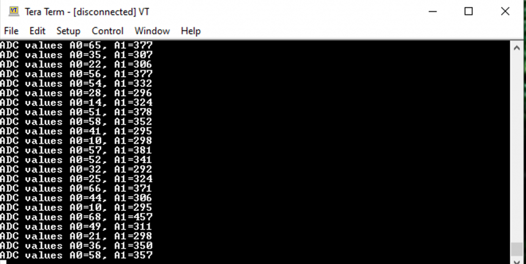
The values shall be update each 2 seconds
Happy coding 🙂
Add Comment