1.What is a PID Controller?
The term PID stands for proportional integral derivative and it is one kind of device used to control different process variables like pressure, flow, temperature, and speed in industrial applications. In this controller, a control loop feedback device is used to regulate all the process variables.
This type of control is used to drive a system in the direction of an objective location otherwise level. It is almost everywhere for temperature control and used in scientific processes, automation & myriad chemical. In this controller, closed-loop feedback is used to maintain the real output from a method like close to the objective otherwise output at the fixe point if possible. In this article, the PID controller design with control modes used in them like P, I & D are discussed.
History
The history of the PID controller is, In the year 1911, the first PID controller was developed by Elmer Sperry. After that, TIC (Taylor Instrumental Company) was implemented a former pneumatic controller with completely tunable in the year1933. After a few years, control engineers removed the error of steady-state that is found within proportional controllers through retuning the end to some false value until the error wasn’t zero.
This retuning included the error which is known as the proportional-Integral controller. After that, in the year 1940, the first pneumatic PID controller was developed through a derivative action to reduce overshooting problems.
In 1942, Ziegler & Nichols have introduced tuning rules to discover and set the suitable parameters of PID controllers by the engineers. At last, automatic PID controllers were extensively used in industries in the mid of 1950.
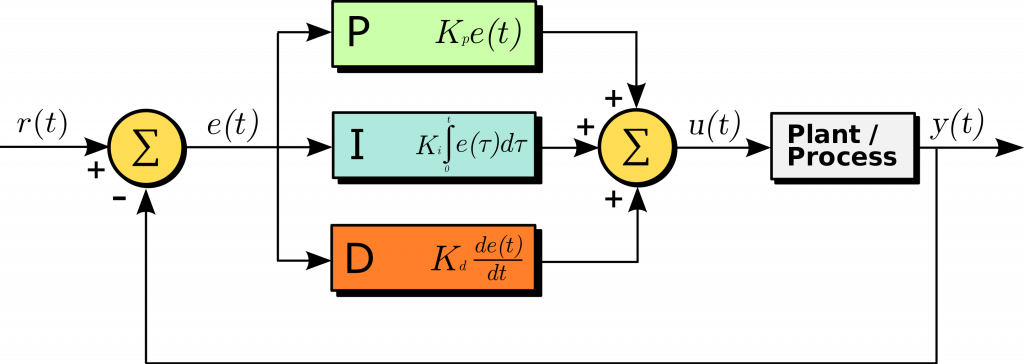
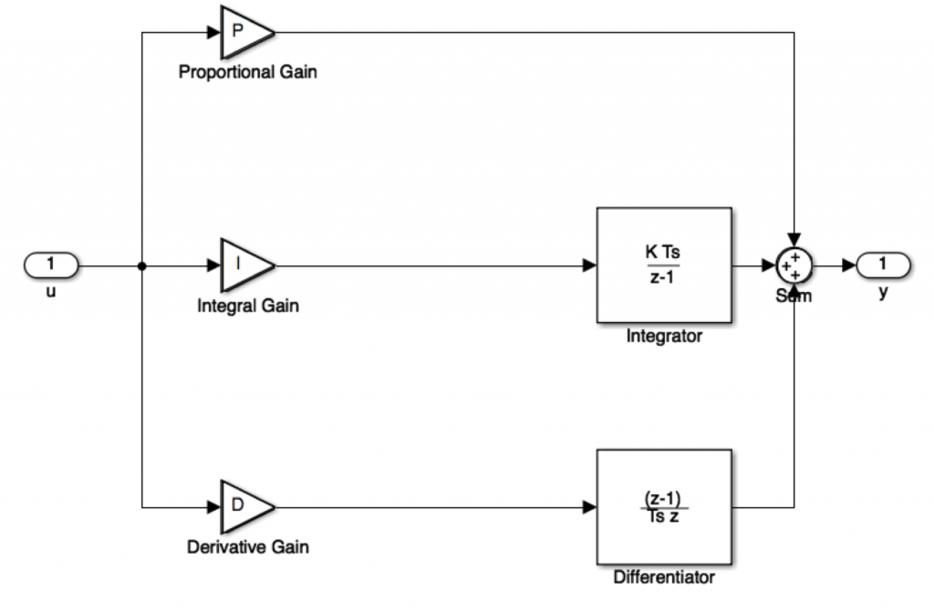
PID Controller Block Diagram
A closed-loop system like a PID controller includes a feedback control system. This system evaluates the feedback variable using a fixed point to generate an error signal. Based on that, it alters the system output. This procedure will continue till the error reaches Zero otherwise the value of the feedback variable becomes equivalent to a fixed point.
This controller provides good results as compared with the ON/OFF type controller. In the ON/OFF type controller, simply two conditions are obtainable to manage the system. Once the process value is lower than the fixed point, then it will turn ON. Similarly, it will turn OFF once the value is higher than a fixed value. The output is not stable in this kind of controller and it will swing frequently in the region of the fixed point. However, this controller is more steady & accurate as compared to the ON/OFF type controller.
Working of PID Controller
With the use of a low cost simple ON-OFF controller, only two control states are possible, like fully ON or fully OFF. It is used for a limited control application where these two control states are enough for the control objective. However oscillating nature of this control limits its usage and hence it is being replaced by PID controllers.
PID controller maintains the output such that there is zero error between the process variable and setpoint/ desired output by closed-loop operations. PID uses three basic control behaviors that are explained below.
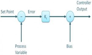
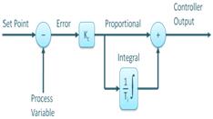
P- Controller
Proportional or P- controller gives an output that is proportional to current error e (t). It compares the desired or set point with the actual value or feedback process value. The resulting error is multiplied with a proportional constant to get the output. If the error value is zero, then this controller output is zero.
This controller requires biasing or manual reset when used alone. This is because it never reaches the steady-state condition. It provides stable operation but always maintains the steady-state error. The speed of the response is increased when the proportional constant Kc increases.
I-Controller
Due to the limitation of p-controller where there always exists an offset between the process variable and setpoint, I-controller is needed, which provides necessary action to eliminate the steady-state error. It integrates the error over a period of time until the error value reaches zero. It holds the value to the final control device at which error becomes zero.
Integral control decreases its output when a negative error takes place. It limits the speed of response and affects the stability of the system. The speed of the response is increased by decreasing integral gain, Ki.
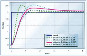
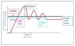
In the above figure, as the gain of the I-controller decreases, the steady-state error also goes on decreasing. For most of the cases, the PI controller is used particularly where the high-speed response is not required.
While using the PI controller, I-controller output is limited to somewhat range to overcome the integral wind up conditions where the integral output goes on increasing even at zero error state, due to nonlinearities in the plant.
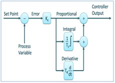
D-Controller
I-controller doesn’t have the capability to predict the future behavior of error. So it reacts normally once the setpoint is changed. D-controller overcomes this problem by anticipating the future behavior of the error. Its output depends on the rate of change of error with respect to time, multiplied by derivative constant. It gives the kick start for the output thereby increasing system response.
In the above figure response of D, the controller is more, compared to the PI controller, and also settling time of output is decreased. It improves the stability of the system by compensating for phase lag caused by I-controller. Increasing the derivative gain increases the speed of response.
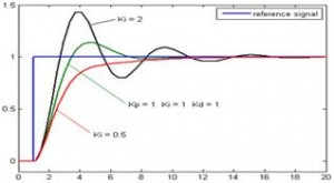
So finally we observed that by combining these three controllers, we can get the desired response for the system. Different manufacturers design different PID algorithms.
2. PID calculation:
The equation of discrete PID controller is:
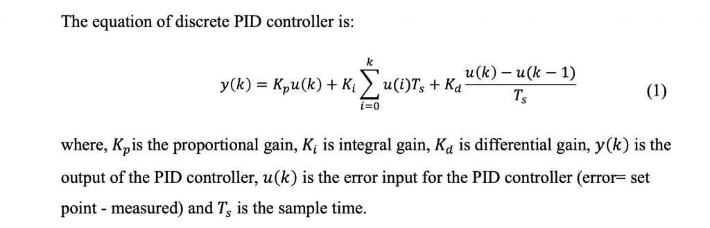
In part 2, we shall see how to implement the PID on our STM32 and in part 3, we shall implement small experiment using PID controller
Add Comment