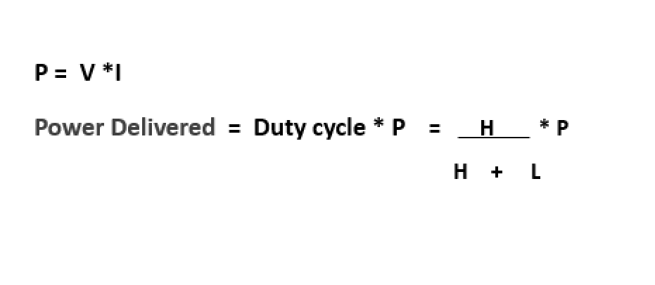
PWM operates by creating a digital output wave of a fixed frequency while allowing varying duty cycle. This gives the microcontroller the capability to vary the amount of power delivered to a load such as a motor. The figure below shows three waveforms indicating their high (H) cycle and low (L) cycles. If you observe carefully, you will really that the sum L+H is constant- all three waveforms have the same frequency but different duty cycles.
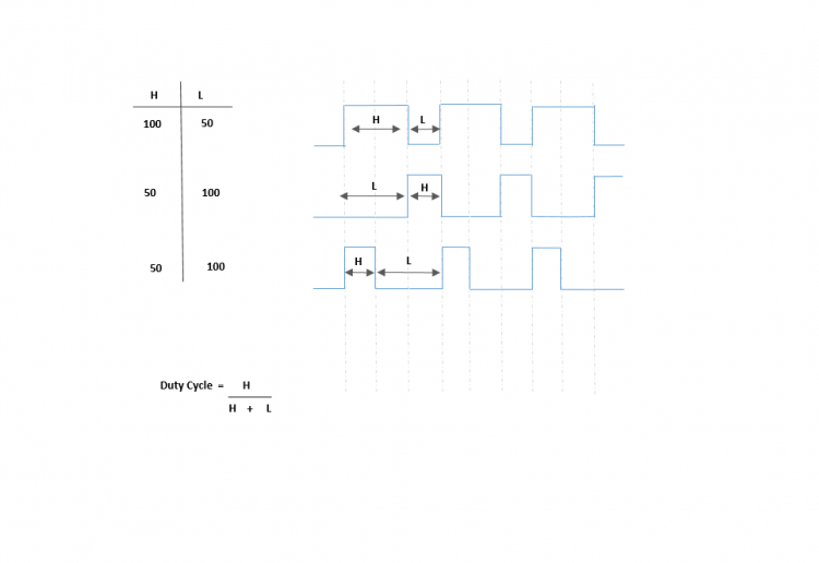
Because the selected frequency of he PWM is often high enough, the high-low togging of the power supplied to a load such as a DC, does not cause the motor to start and stop continuously- it responds to the overall average of the wave. The average value of the PWM signal is linearly proportional to the duty cycle and is not affected by the frequency.
Programming PWM on Tiva C LaunchPad
The Tiva C launchPad comes with 2 PWM modules. Each PWM module provides 4 PWM generators and each generator has its own counter. Each generator has 2 output pins thus each module provides us with 8 PWM pins.
Setting Up the PWM
- We must disable the PWM before configure it. We do this with the PWMx control registe
- Enable the clock source of the PWM module using the RCGCPWM register. – To enable PWM Module 0, we need to set the bit0 of the RCGCPWM register to 1. To enable PWM Module 1, we need to set bit1 of the RCGCPWM regsiter to 1.
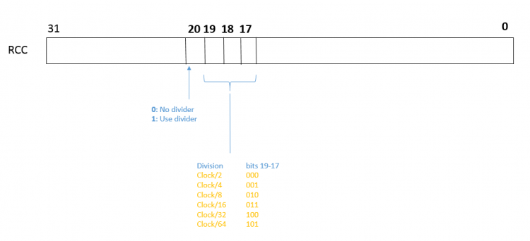
- Configure the Run-Mode Clock Configuration register – This register is used to divide the system clock before feeding it to the PWM module. We can also choose to use the system clock without a divider, we do this by setting bit20 of the RCC register to 0. If we set bit20 of RCC to 1, we must go ahead to configure bits 19-17 according to the divider size we want.
Add Comment