In this guide, we shall take a look at the thermocouple and how this type of sensor works and use MAX6675 thermocouple to measure the temperature.
In this guide, we shall cover the following:
- Thermocouple typeK
- MAX6675.
- Connection MAX6675 with STM32.
- Code.
- Result
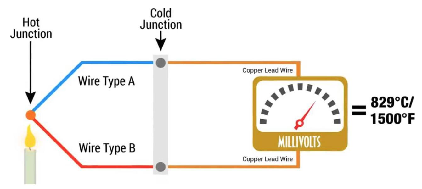
1. Thermocouple:
Type K Thermocouple provides widest operating temperature range. It consist of positive leg which is non-magnetic and negative leg which is magnetic.In K Type Thermocouple traditional base metal is used due to which it can work at high temperature and can provide widest operating temperature range. One of the constituent metal in K Type Thermocouple is Nickel, which is magnetic in nature.

The characteristic shown by K Type Thermocouple is that they undergo a deviation in output when magnetic material reaches its Curie Point, at around 185 °C. K Type thermocouple work very well in oxidizing atmosphere at temperatures up to 1260°C (2300°F) and its tolerance class is ± 1.5 K between -40 and 375 °C.

Why To prefer K Type Thermocouple
- One of the major advantage of K type thermocouple over other thermocouple’s is it can function in rugged environmental condition & in various atmospheres
- It has integrated composition of Chromel and Alumel wires has a range of -270 °C to 1260°C and an output of -6.4 to 9 mV over maximum temperature range.
- Also known as general purpose thermocouple due to its wide range of temperature
- Type K has a longer life than Type J as in Type J Fe (iron) wire oxidizes rapidly, especially at higher temperature
- They are inexpensive.
- Have a fast response
- Small in size and are reliable.
- Generally used at temperatures above 540 degrees C
Composition of K Type Thermocouple
In K Type Thermocouple positive leg is composed of 90% nickel, 10%chromium and a negative leg is composed of 95% nickel, 2% aluminum, 2% manganese and 1% silicon. These are the most common general purpose thermocouple with a sensitivity of approx 41µV/°C.
Type K Insulation Material
In Type K Thermocouple mainly two type of insulation is used firstly Ceramic beads insulation is used as it is a lightweight insulating product. It is made from high purity alumino-silicate materials. It has low thermal mass which means that it does not retain heat, low thermal conductivity and is an extremely effective insulation material as it can withstand high temperature of 1260 °C so it it best suited material for Type K thermocouple.
Secondly compacted mineral insulation and outer metal sheath (MgO) is used. Magnesium Oxide has a high dielectric strength, responds quickly to temperature changes and is very durable. It has typical Composition of the Standard Quality MgO (97%) and the High Purity MgO and AI2O3.
Magnesium Oxide insulation is recommended for K Type thermocouple when Thermocouple are to be immersed in liquids, high moisture, corrosive gases or high pressures. The thermocouple can be formed to reach otherwise inaccessible areas.

Temperature Range
To find appropriate range of thermocouple we should use appropriate wire because different wires measure various temperature ranges. Of the four major thermocouple types, type K covers the widest range :–
- Thermocouple grade wire, –454 to 2,300F (–270 to1260°C)
- Extension wire, 32 to 392F (0 to200°C)
Accuracy (whichever is greater)
- Standard: +/- 2.2°C or +/-.75%
- Special Limits of Error: +/– l°C or0.4%
Tolerance Class

EMF Vs Temperature Graph for K Type Thermocouple

Pros And Cons:
Pros
- To measure temperature it provide good linearity of emf
- It provide good resistance aganist oxidation below 1000 °C(1600°F).
- Highly stable output
- Comparitively cost effective than other thermocouple.
Cons
- Not suitable for reducing atmosphere but can withstand metallic
- Aging of the emf characteristic, when compared to noble metal thermocouples (B, R, andS).
- Not suitable for vacuum applications due to vaporization of chromium in the positive element.
- Green-Rotis phenomenon may occur due to low oxygen level for the thermocouples which are used between 815°C to 1040°C (1500°F to1900°F).
- Type K thermocouples should not be used in Sulphuric environment since both elements will rapidly corrode and the negative element will eventually fail mechanically due to becoming brittle.
Uses of K Type Thermocouple
They are mostly used for applications at temperatures above 550 °C up to the maximum working pressure of the thermocouple.
- They are used in many industries like Steel & Iron to monitor temperature & chemistry through out the steel making process
- Used for testing temperatures associated with process plants e.g. chemical production and petroleum refineries
- Used for Testing of heating appliance safety
- Type K is commonly used in nuclear applications because of its relative radiation hardness.
2. MAX6675:
The MAX6675 performs cold-junction compensation and digitizes the signal from a type-K thermocouple. The data is output in a 12-bit resolution, SPI-compatible, read-only format.
This converter resolves temperatures to 0.25°C, allows readings as high as +1024°C, and exhibits thermocouple accuracy of 8 LSBs for temperatures ranging from 0°C to +700°C.
Applications
● Industrial ● Appliances ● HVAC
Features
● Direct Digital Conversion of Type -K Thermocouple Output
● Cold-Junction Compensation
● Simple SPI-Compatible Serial Interface ● 12-Bit, 0.25°C Resolution
● Open Thermocouple Detection
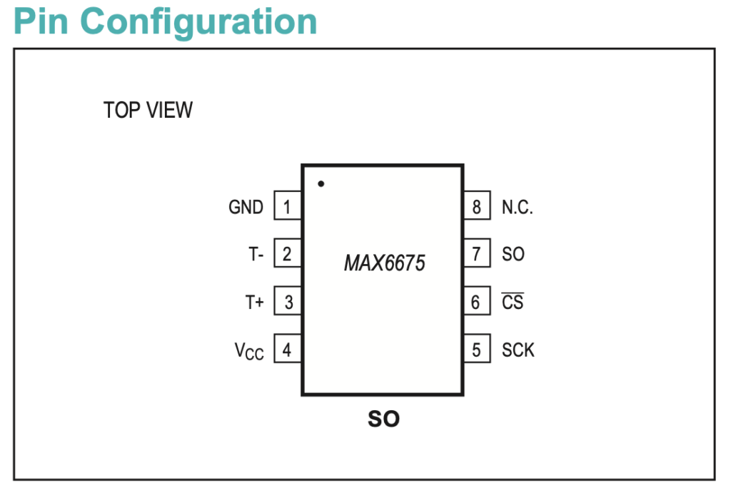
Pin Configuration:
Typical connection:
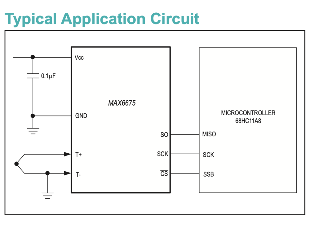
As seen, it requires minimal external components to make the converter works with our STM32.
Serial Output of MAX6675:
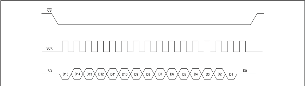
As seen from the picture, the converter requires CLK, CS and SO.
This can be achieved with software level.
3. Connection MAX6675 with STM32:
In this guide, we shall use OLED SSD1306 I2C to display the temperature (code from this topic)
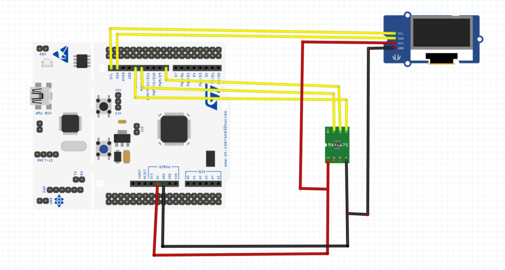
The connection as following:
| MAX6675 | STM32F411 |
| SCK | PA5 |
| SO | PA6 |
| CS | PA9 |
4. Code:
We start of by creating header file named MAX6675.h and the following the code:
#ifndef __MAX6675__h
#define __MAX6675__h
#include "stdint.h"
#define NAN 		 -1000
void max6675_init(void);
float ReadMAX6675_C(void);
float ReadMAX6675_F(void);

#endif
For MAX6675.c as following:
#include "max6675.h"
#include "stm32f4xx.h"                  // Device header
#include "delay.h"
#include "stdlib.h"
#include "stdio.h"

#define SCK_HIGH GPIOA->BSRR=GPIO_BSRR_BS5
#define SCK_LOW  GPIOA->BSRR=GPIO_BSRR_BR5

#define CS_HIGH GPIOA->BSRR=GPIO_BSRR_BS9
#define CS_LOW  GPIOA->BSRR=GPIO_BSRR_BR9

static uint8_t read_sensor()
	{
	int i;
  uint8_t d = 0;
for (i = 7; i >= 0; i--) {
    SCK_LOW;
   delayuS(10);
    if (GPIOA->IDR &GPIO_IDR_ID6) {
      // set the bit to 0 no matter what
      d |= (1 << i);
    }

    SCK_HIGH;
    delayuS(10);
  }

  return d;

	}


void max6675_init(void)
	{
	RCC->AHB1ENR|=RCC_AHB1ENR_GPIOAEN;
	GPIOA->MODER|=GPIO_MODER_MODE5_0|GPIO_MODER_MODE9_0;
	GPIOA->MODER&=~(GPIO_MODER_MODE5_1|GPIO_MODER_MODE9_1|GPIO_MODER_MODE6_0|GPIO_MODER_MODE6_1);
	CS_HIGH;
	}

float ReadMAX6675_C(void)
	{
	uint16_t v;
	float temp;
	CS_LOW;
	v = read_sensor();
  v <<= 8;
  v |= read_sensor();
	CS_HIGH;
		if (v & 0x4) {
    // uh oh, no thermocouple attached!
    return NAN;
    // return -100;
  }

  v >>= 3;

	temp=v*0.20;
  return temp ;

	}
float ReadMAX6675_F(void) { return (ReadMAX6675_C() * 9.0 / 5.0 + 32); }
In the main function,
#include "oled.h"
#include "test.h"
#include "bitmap.h"
#include "horse_anim.h"
#include "stdio.h"
#include "MAX6675.h"


float temperature;
extern void SysClockConfig(void);
int main(void)
{
SysClockConfig();
SSD1306_Init();
max6675_init();


while(1)
{
	char data[30];
	temperature=ReadMAX6675_C();
	SSD1306_Clear();
	sprintf(data,"%0.1f     ",temperature);
	SSD1306_GotoXY(0,0);
	SSD1306_Puts(data,&Font_11x18, 1);
	SSD1306_UpdateScreen();
	delay(1000);

}


}
You may download the code from here.
5.Results:


It seems my OLED is no longer functioning correctly for one reason or another. However, if you run the code, it should display the temperature on the OLED.
Happy coding 🙂
Add Comment