In this guide, we shall take a look at the DMA which called Direct Memory Access of STM32F7 and how to use it in memory to memory to transfer 4-bytes from 1 memory location to another using DMA.
In this guide, we will cover the following:
- What is DMA
- Code
- Demo
1.1 What is DMA:
Direct memory access (DMA) is used in order to provide high-speed data transfer between peripherals and memory and between memory and memory. Data can be quickly moved by DMA without any CPU action. This keeps CPU resources free for other operations.
DMA main features
The main DMA features are:
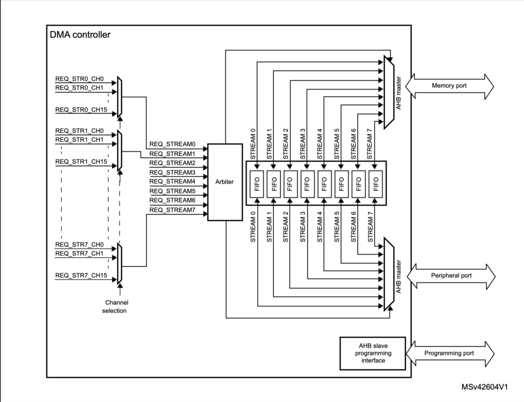
• Dual AHB master bus architecture, one dedicated to memory accesses and one dedicated to peripheral accesses
• AHB slave programming interface supporting only 32-bit accesses
• 8 streams for each DMA controller, up to 16 channels (requests) per stream
• Four-word depth 32 first-in, first-out memory buffers (FIFOs) per stream, that can be used in FIFO mode or direct mode:
– FIFO mode: with threshold level software selectable between 1/4, 1/2 or 3/4 of the FIFO size
– Direct mode: each DMA request immediately initiates a transfer from/to the memory. When it is configured in direct mode (FIFO disabled), to transfer data in memory-to-peripheral mode, the DMA preloads only one data from the memory to the internal FIFO to ensure an immediate data transfer as soon as a DMA request is triggered by a peripheral.
• Each stream can be configured to be:
– a regular channel that supports peripheral-to-memory, memory-to-peripheral and memory-to-memory transfers
– a double buffer channel that also supports double buffering on the memory side
• Priorities between DMA stream requests are software-programmable (4 levels consisting of very high, high, medium, low) or hardware in case of equality (for example, request 0 has priority over request 1)
• Each stream also supports software trigger for memory-to-memory transfers (only available for the DMA2 controller)
• Each stream request can be selected among up to 16 possible channel requests. This selection is software-configurable and allows several peripherals to initiate DMA requests
• The number of data items to be transferred can be managed either by the DMA controller or by the peripheral:
– DMA flow controller: the number of data items to be transferred is softwareprogrammable from 1 to 65535
– Peripheral flow controller: the number of data items to be transferred is unknown and controlled by the source or the destination peripheral that signals the end of the transfer by hardware
• Independent source and destination transfer width (byte, half-word, word): when the data widths of the source and destination are not equal, the DMA automatically packs/unpacks the necessary transfers to optimize the bandwidth. This feature is only available in FIFO mode
• Incrementing or non-incrementing addressing for source and destination
• Supports incremental burst transfers of 4, 8 or 16 beats. The size of the burst is software-configurable, usually equal to half the FIFO size of the peripheral
• Each stream supports circular buffer management
• 5 event flags (DMA half transfer, DMA transfer complete, DMA transfer error, DMA FIFO error, direct mode error) logically ORed together in a single interrupt request for each stream
1.2 DMA Block Diagram:
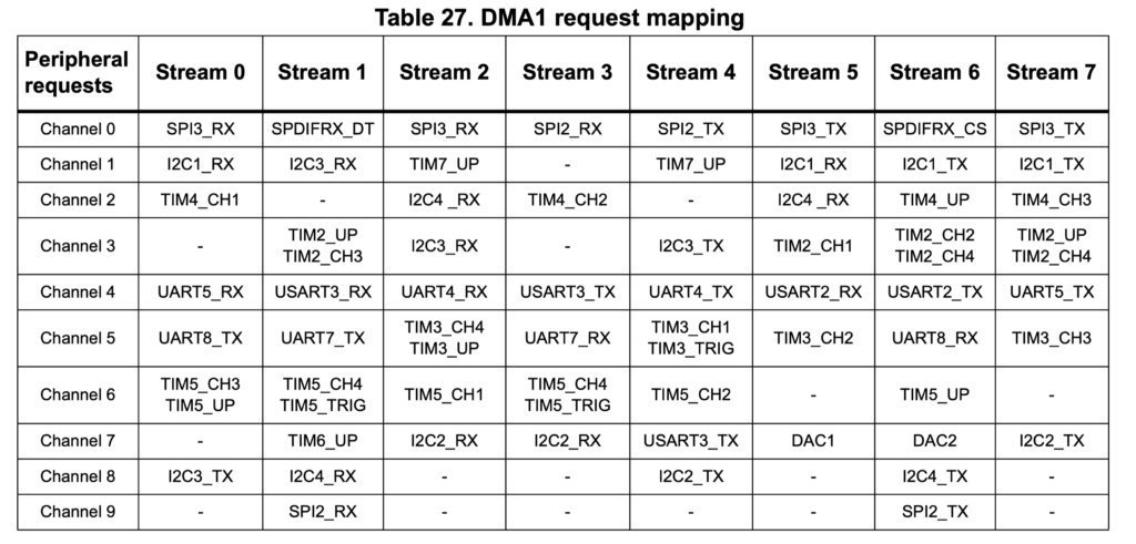
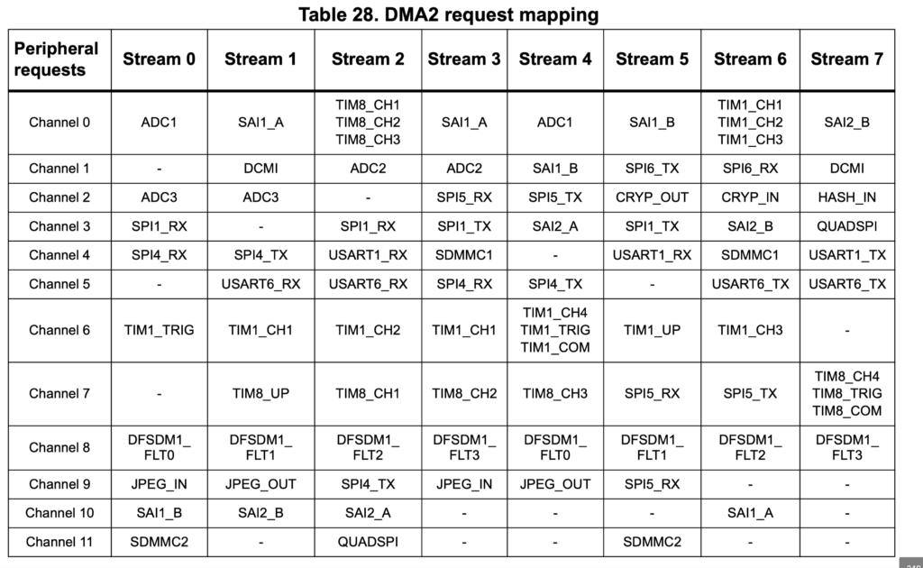
1.3 DMA Map:
1.4 DMA Operation Modes:
The DMA can operate in the different modes:
- Memory to peripheral
- Peripheral to memory
- Memory to Memory
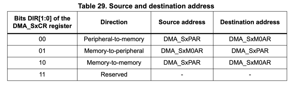
These modes can be selected by during the configuration of the DMA:
You may refer to reference manual for more details about DMA
2. Code:
According to the reference manual, only DMA2 is able to work in Memory to Memory mode
“Only the DMA2 controller is able to perform memory-to-memory transfers.”
First we need to find which bus is DMA2 connected and we can get this from the datasheet of STM32F767.
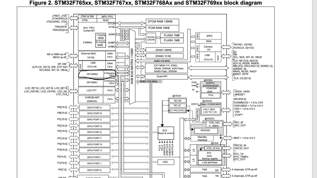
Hence we can start of by enabling clock access to DMA2
	//Enable DMA2 clock access
	RCC->AHB1ENR|=RCC_AHB1ENR_DMA2EN;
Disable DMA2_Stream0 as following:
	DMA2_Stream0->CR=0x00;
	//wait until
	while(DMA2_Stream0->CR & DMA_SxCR_EN){;}
Then we can configure the DMA stream with the following parameters:
- Memory and peripheral size to 16-bit
- Memory and peripheral increment
- Direct is memory to memory
- Transfer complete interrupt
- Set the FIFO to full threshold
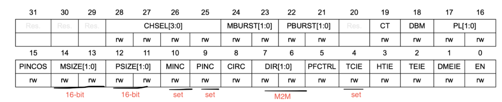
	DMA2_Stream0->CR|=DMA_SxCR_MSIZE_0
	|DMA_SxCR_PSIZE_0|DMA_SxCR_MINC|DMA_SxCR_PINC
	|DMA_SxCR_DIR_1|DMA_SxCR_TCIE|DMA_SxCR_TEIE|DMA_SxCR_DMEIE;
	DMA2_Stream0->FCR |= DMA_SxFCR_DMDIS;
  DMA2_Stream0->FCR |= (DMA_SxFCR_FTH_0 | DMA_SxFCR_FTH_1);
	NVIC_EnableIRQ(DMA2_Stream0_IRQn);
For interrupt handler
//DMA2 interrupt handler
	void DMA2_Stream0_IRQHandler(void)
			{
			if((DMA2->LISR)&DMA_LISR_TCIF0)
					{
					//set finished to 1
					finished=1;
					//clear transfer complete interrupt
					DMA2->LIFCR=DMA_LIFCR_CTCIF0;
					}
			if((DMA2->LISR)&DMA_LISR_TEIF0)
					{
					//transfer error interrupt
					DMA2->LIFCR=DMA_LIFCR_CTEIF0;
					}

			if((DMA2->LISR)&DMA_LISR_DMEIF0)
					{
				//direct mode error
					DMA2->LIFCR=DMA_LIFCR_CDMEIF0;
					}

			}
For data transfer:
void send_data(uint32_t src, uint32_t des, uint16_t len)
	{
	DMA2_Stream0->PAR=(uint32_t)src;
	DMA2_Stream0->M0AR=(uint32_t)des;
	DMA2_Stream0->NDTR=len;
	DMA2_Stream0->CR|=DMA_SxCR_EN;

	}
in while loop we can transfer the data as following:
		for (int i=0;i<4;i++)
				{
				data_s[i]=var;
				}
			send_data((uint32_t)data_s,(uint32_t)data_r,4);
			var++;
			while(finished==0){;}
			finished=0;
				for (int j=0;j<400000;j++);
Hence, the entire code is as following:
/**
 ******************************************************************************
 * @file           : main.c
 * @author         : Auto-generated by STM32CubeIDE
 * @brief          : Main program body
 ******************************************************************************
 * @attention
 *
 * Copyright (c) 2022 STMicroelectronics.
 * All rights reserved.
 *
 * This software is licensed under terms that can be found in the LICENSE file
 * in the root directory of this software component.
 * If no LICENSE file comes with this software, it is provided AS-IS.
 *
 ******************************************************************************
 */
#include "stm32f7xx.h"


//data to be send
uint16_t data_s[4];
//data to be received
uint16_t data_r[4];
uint16_t var=2;
//indicate that DMA finished transfered to out application
volatile uint8_t finished=0;


void send_data(uint32_t src, uint32_t des, uint16_t len)
	{
	DMA2_Stream0->PAR=(uint32_t)src;
	DMA2_Stream0->M0AR=(uint32_t)des;
	DMA2_Stream0->NDTR=len;
	DMA2_Stream0->CR|=DMA_SxCR_EN;

	}


int main(void)
	{
	//Enable DMA2 clock access
	RCC->AHB1ENR|=RCC_AHB1ENR_DMA2EN;
	//reset DMA2_stream0
	DMA2_Stream0->CR=0x00;
	//wait until
	while(DMA2_Stream0->CR & DMA_SxCR_EN){;}
	/*set memory and peripheral size to 16-bit,
	Memory increment, peripheral increment,
	direction memory to memory and transfer complete interrupt
	*/
	DMA2_Stream0->CR|=DMA_SxCR_MSIZE_0
	|DMA_SxCR_PSIZE_0|DMA_SxCR_MINC|DMA_SxCR_PINC
	|DMA_SxCR_DIR_1|DMA_SxCR_TCIE|DMA_SxCR_TEIE|DMA_SxCR_DMEIE;
	DMA2_Stream0->FCR |= DMA_SxFCR_DMDIS;
  DMA2_Stream0->FCR |= (DMA_SxFCR_FTH_0 | DMA_SxFCR_FTH_1);
	NVIC_EnableIRQ(DMA2_Stream0_IRQn);

	while(1)
		{
		for (int i=0;i<4;i++)
				{
				data_s[i]=var;
				}
			send_data((uint32_t)data_s,(uint32_t)data_r,4);
			var++;
			while(finished==0){;}
			finished=0;
				for (int j=0;j<400000;j++);

		}


	}
	//DMA2 interrupt handler
	void DMA2_Stream0_IRQHandler(void)
			{
			if((DMA2->LISR)&DMA_LISR_TCIF0)
					{
					//set finished to 1
					finished=1;
					//clear transfer complete interrupt
					DMA2->LIFCR=DMA_LIFCR_CTCIF0;
					}
			if((DMA2->LISR)&DMA_LISR_TEIF0)
					{
					//transfer error interrupt
					DMA2->LIFCR=DMA_LIFCR_CTEIF0;
					}

			if((DMA2->LISR)&DMA_LISR_DMEIF0)
					{
				//direct mode error
					DMA2->LIFCR=DMA_LIFCR_CDMEIF0;
					}

			}
3. Demo:
Happy coding 🙂
Add Comment