Analog-to-digital converters are among the most widely used devices for data acquisition. Digital computers use binary (or discrete) values, but in the physical world everything is analog (or continuous). Temperature, pressure (wind or liquid), humidity, and velocity are a few examples of physical quantities that we deal with every day. A physical quantity is converted to electrical (voltage, current) signals using a device called a transducer. Transducers used to generate electrical outputs are also referred to as sensors. Sensors for temperature, velocity, pressure, light, and many other natural physical quantities produce an output that is voltage (or current). Therefore, we need an analog-to-digital converter to translate the analog signals to digital numbers so that the microcontroller can read and process the numbers.
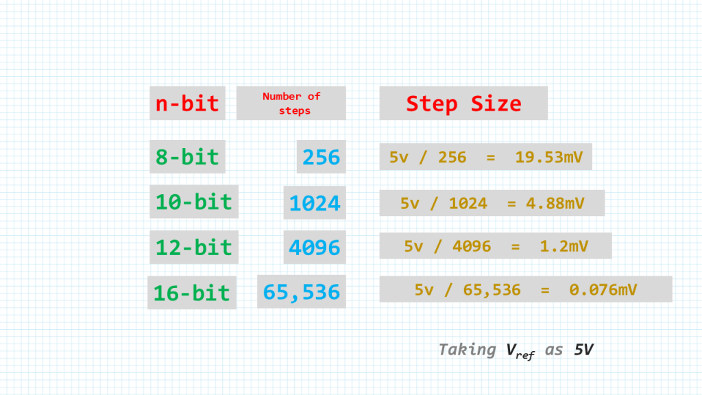
The ADC has n-bit resolution, where n can be 8, 10, 12, 16, or even 24 bits. Higher-resolution ADCs provide a smaller step size, where step size is the smallest change that can be detected by an ADC.
This table here show the number steps as well as the step size give the number of bits the adc has.
Vref is an input voltage used for the reference voltage. The voltage connected to this pin, along with the resolution of the ADC chip, determine the step size. For an 8-bit ADC, the step size is Vref / 256 because it is an 8-bit ADC, and 2 to the power of 8 gives us 256 steps.
STM32F411-NUCLEO
#include "stm32f4xx.h"

int main (void) {
    int result;

    /* set up pin PA5 for LED */
    RCC->AHB1ENR |=  1;	            /* enable GPIOA clock */
    GPIOA->MODER &= ~0x00000C00;    /* clear pin mode */
    GPIOA->MODER |=  0x00000400;    /* set pin to output mode */

    RCC->AHB1ENR |=  1;
    GPIOA->MODER |=  0xC;

    /* setup ADC1 */
    RCC->APB2ENR |= 0x00000100;     /* enable ADC1 clock */
    ADC1->CR2 = 0;                  /* SW trigger */
    ADC1->SQR3 = 1;
    ADC1->SQR1 = 0;
    ADC1->CR2 |= 1;

    while (1) {
        ADC1->CR2 |= 0x40000000;        /* start a conversion */
        while(!(ADC1->SR & 2)) {}       /* wait for conv complete */
        result = ADC1->DR;              /* read conversion result */
        if (result > 1500)
            GPIOA->BSRR = 0x00000020;   /* turn on LED */
        else
            GPIOA->BSRR = 0x00200000;   /* turn off LED */
    }
}
Add Comment