
Ever heard of MPU-9250? It is a multi-chip module (MCM) which consists of 2 dies, and houses the 3-Axis gyroscope and the 3-Axis accelerometer! Still unsure about how it works? Read on to find out! Hope that this article will help you understand the applications of MPU9250 and how to interface it with STM32 and use OLED to display the acceleration !
In this guide, we shall cover the following:
- MPU9250
- Connection diagram
- Initializing the MPU9250
- Reading the values
- Demo
1. MPU9250:
Accelerometer Working Principle
An Accelerometer measures the rate of change of velocity of an object with respect to time also known as acceleration. With an accelerometer, you are able to figure out the angle the sensor is tilted at with respect to the ground.
An accelerometer has microscopic crystals that go under stress when vibrations occur. From that stress, a voltage is generated which creates a reading on any acceleration. The unit of measurement for acceleration is meter per second squared (m/s^2). But as accelerometer sensors express measurements in “g”, one “g” is the value of the earth gravitational force which is equal to 9.8 meters per second squared.
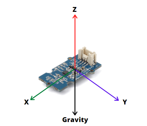
For example, in a 3 axis accelerometer like the MPU9250 Accelerometer sensor, when placed flat with the Z-axis pointing up, Z-axis output of sensor = 1 g or 9.8m/s^2 while X and Y = 0. This is due to the gravitational force being perpendicular to these axes which do not affect them.
From this data, the sensor is able to use simple trigonometry math and calculate the angle of the sensor.
Gyroscope Working Principle
The Gyroscope which measures rotational velocity/rate of change of angular position over time works through the Coriolis effect and MEMS technology.
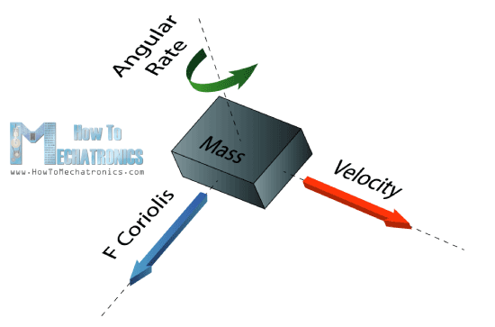
When a mass is moving in a particular direction with a particular velocity and when an external angular rate will be applied as shown with the green arrow a force will occur which the sensor will detect.
As shown above, labelled by the blue and red arrow, this will cause perpendicular displacement of the mass. The displacement will cause a change in capacitance which will be measured, processed and it will correspond to a particular angular rate.
The outputs of the gyroscope are in degrees per second, so in order to get the angular position, we just need to integrate the angular velocity.
For a full explanation of how a Gyroscope works, you can check out Elprocus page here.
About the MPU9250 IMU (Inertial Measurement Unit)
IMU which stands for Inertial Measurement Unit is defined as a 9-axis sensor that measures orientation, velocity, and gravitational forces by combining Accelerometer, Gyroscope, and Magnetometer into one. IMUs typically come in large packages, but with recent developments like MEMS technology, they are now more commonly seen as miniaturized sensors designed for easy integration with Arduino or other microcontrollers.
In today’s tutorial, we will be using an IMU that is a 9-axis motion tracking module based on MPU-9250.
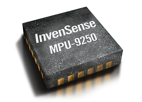
The MPU-9250 is a 9-axis MEMS sensor from InvenSense®. The MPU-9250 features:
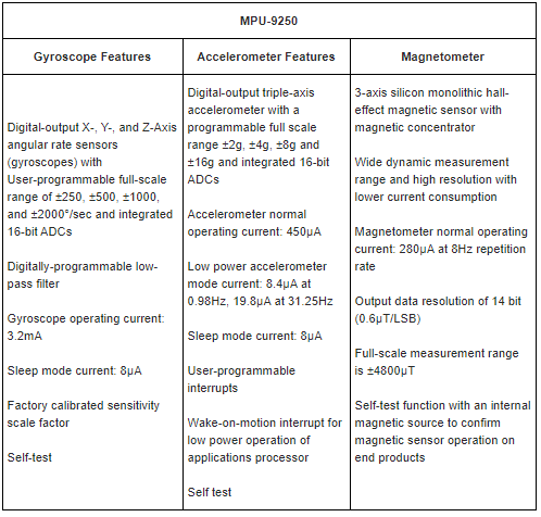
Additional Features of the MPU9250 includes:
- Smallest and thinnest QFN package for portable devices: 3x3x1mm
- Auxiliary master I2C bus for reading data from external sensors
- Minimal cross-axis sensitivity between the accelerometer, gyroscope and magnetometer axes
- 512 byte FIFO buffer enables the applications processor to read the data in bursts
- Digital-output temperature sensor
- 10,000 g shock tolerant
- 400kHz Fast Mode I2C for communicating with all registers
- Serial interfaces:
- 1MHz for communicating with all registers
- 200MHz for reading sensor and interrupt registers
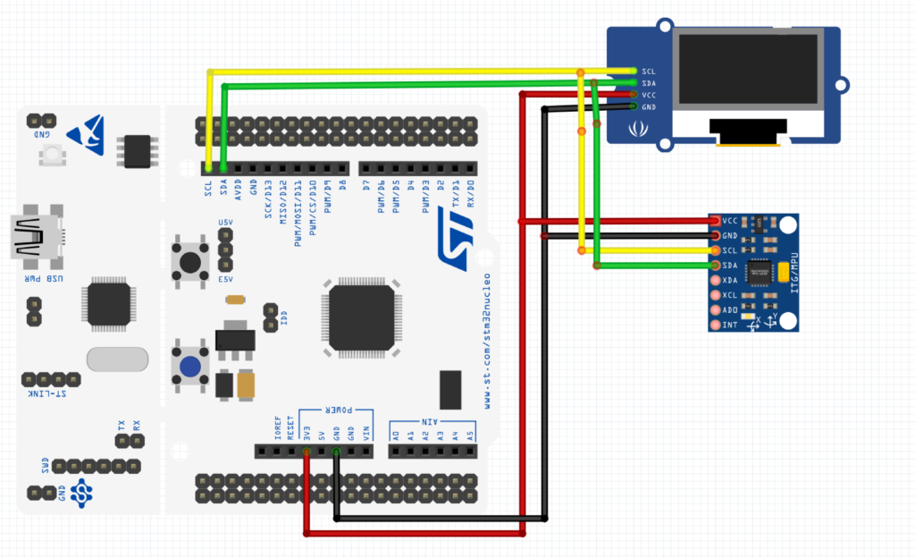
2. Connection Diagram:
In this guide, we need the following:
- STM32F411 Nuclei-64
- OLED SSD1306 I2C
- MPU9250
3. Initializing MPU9250:
Since the sensor has three build-in sensor which they are
- Accelerometer
- Gyroscope
- Magnetometer
We need to initialize each one them separately
For the accelerometer, we need only to specify the acceleration range, we could use simple define statement as following:
#define ACC_FULL_SCALE_2_G       0x00
#define ACC_FULL_SCALE_4_G       0x08
#define ACC_FULL_SCALE_8_G       0x10
#define ACC_FULL_SCALE_16_G      0x18
Then we can call the initialize of accelerometer as following:
void MPU9250_beginAccel(uint8_t mode) {
  switch(mode) {
  case ACC_FULL_SCALE_2_G:
    accelRange = 2.0;
    break;
  case ACC_FULL_SCALE_4_G:
    accelRange = 4.0;
    break;
  case ACC_FULL_SCALE_8_G:
    accelRange = 8.0;
    break;
  case ACC_FULL_SCALE_16_G:
    accelRange = 16.0;
    break;
  default:
    return; // Return without writing invalid mode
  }
  i2c_writeByte(address, MPU9250_ADDR_ACCELCONFIG, mode); //write the mode

}
we can do the same for gyroscope
We declare some define statements
#define GYRO_FULL_SCALE_250_DPS  0x00
#define GYRO_FULL_SCALE_500_DPS  0x08
#define GYRO_FULL_SCALE_1000_DPS 0x10
#define GYRO_FULL_SCALE_2000_DPS 0x18
then we can call initialize the gyroscope:
void MPU9250_beginGyro(uint8_t mode) {

  switch (mode) {
  case GYRO_FULL_SCALE_250_DPS:
    gyroRange = 250.0;
    break;
  case GYRO_FULL_SCALE_500_DPS:
    gyroRange = 500.0;
    break;
  case GYRO_FULL_SCALE_1000_DPS:
    gyroRange = 1000.0;
    break;
  case GYRO_FULL_SCALE_2000_DPS:
    gyroRange = 2000.0;
    break;
  default:
    return; // Return without writing invalid mode
  }
  i2c_writeByte(address, 27, mode);

}
for the magnetometer,
#define MAG_MODE_POWERDOWN        0x0
#define MAG_MODE_SINGLE           0x1
#define MAG_MODE_CONTINUOUS_8HZ   0x2
#define MAG_MODE_EXTERNAL         0x4
#define MAG_MODE_CONTINUOUS_100HZ 0x6
#define MAG_MODE_SELFTEST         0x8
#define MAG_MODE_FUSEROM          0xF
#define AK8963_ADDRESS  0x0C
#define AK8963_RA_HXL   0x03
#define AK8963_RA_CNTL1 0x0A
#define AK8963_RA_ASAX  0x10
void magWakeup(void) {
   char bits;
  i2c_readByte(address, MPU9250_ADDR_PWR_MGMT_1, &bits);
  bits &= ~0b01110000; // Turn off SLEEP, STANDBY, CYCLE
  i2c_writeByte(address, MPU9250_ADDR_PWR_MGMT_1, bits);

}

void magEnableSlaveMode(void) {
   char bits;

  i2c_readByte(address, MPU9250_ADDR_INT_PIN_CFG, &bits);
  bits |= 0b00000010; // Activate BYPASS_EN
  i2c_writeByte(address, MPU9250_ADDR_INT_PIN_CFG, bits);

}

float adjustMagValue(int16_t value, uint8_t adjust) {
  return ((float) value * (((((float) adjust - 128) * 0.5) / 128) + 1));
}

float MPU9250_magX(void) {
  return adjustMagValue(MPU9250_magGet(1, 0), magXAdjust) + magXOffset;
}

float MPU9250_magY(void) {
  return adjustMagValue(MPU9250_magGet(3, 2), magYAdjust) + magYOffset;
}

float MPU9250_magZ(void) {
  return adjustMagValue(MPU9250_magGet(5, 4), magZAdjust) + magZOffset;
}

float MPU9250_magHorizDirection(void) {
  return atan2(MPU9250_magX(), MPU9250_magY()) * 180 / Pi;
}

uint8_t MPU9250_magUpdate(void) {

	i2c_ReadMulti(AK8963_ADDRESS,0x03,7,(char*)magBuf);


  return 0;
}

void MPU9250_beginMag(uint8_t mode) {

  magWakeup();
  magEnableSlaveMode();
  magReadAdjustValues();
  magSetMode(MAG_MODE_POWERDOWN);
  magSetMode(mode);

}
In this guide, we shall see how to read the accelerometer part
4.Reading the acceleration values:
In order to read the acceleration part, we need to read 6 registers that contain the acceleration as following:
uint8_t MPU9250_accelUpdate(void) {
	i2c_ReadMulti(address,0x3B,6,accelBuf);

	return 0;

}
Then we can use simple equation to extract each acceleration value as following:
float MPU9250_accelGet(uint8_t highIndex, uint8_t lowIndex) {
  int16_t v = ((int16_t) accelBuf[highIndex]) << 8 | accelBuf[lowIndex];
  return ((float) -v) * accelRange / (float) 0x8000; // (float) 0x8000 == 32768.0
}

float MPU9250_accelX(void) {
  return MPU9250_accelGet(0, 1);
}

float MPU9250_accelY(void) {
  return MPU9250_accelGet(2, 3);
}

float MPU9250_accelZ(void) {
  return MPU9250_accelGet(4, 5);
}
In main loop, we call MPU9250_accelUpdate
MPU9250_accelUpdate();
acc_x=MPU9250_accelX();
acc_y=MPU9250_accelY();
acc_z=MPU9250_accelZ();
Then we can display the results on the OLED screen (here a non-blocking delay is used)
if(millis()-previous>update_rate){
previous=millis();
//SSD1306_Clear();
SSD1306_GotoXY (0,0);
sprintf(zz,"Acc X=%0.3f",acc_x);
SSD1306_Puts (zz, &Font_11x18, 1);

SSD1306_GotoXY (0,20);
sprintf(zz,"Acc Y=%0.3f",acc_y);
SSD1306_Puts (zz, &Font_11x18, 1);

SSD1306_GotoXY (0,40);
sprintf(zz,"Acc Z=%0.3f",acc_z);
SSD1306_Puts (zz, &Font_11x18, 1);

SSD1306_UpdateScreen();
}
You may download the code from here:
5. Demo:
Happy coding 🙂
2 Comments
the code does not work for me i don’t know why
Hi,
what is the issue?
Add Comment