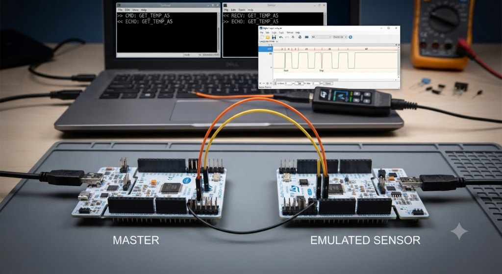
This guide walks through building a lightweight, framed UART protocol for emulating a sensor, covering the frame layout, parser design, and error handling needed to reliably transfer configuration data between a master MCU and an emulated sensor. By the end, you’ll have a clean, modular .c/.h implementation you can drop into both STM32 projects and extend toward full sensor emulation.
In this guide, we shall cover the following:
- Protocol explanation.
- Protocol development.
1. Protocol Explanation:
Let’s step back and look at the protocol as a design, not just code. This will pay off when you start adding real sensor behavior.
1.1. Why a Framed Protocol At All?
You could keep sending raw strings like the echo demo, but you’d hit four problems immediately:
| Problem | Raw Bytes | Framed Protocol |
|---|---|---|
| Resync after a lost byte | Impossible — you don’t know where a message starts | Start byte lets the parser re-align |
| Boundary detection | Only works because of \r\n conventions | Explicit length field |
| Integrity | None | Checksum |
| Command routing | Must parse text | First byte = command |
A framed protocol is basically a contract between both sides that says: “If you see this exact byte layout, and the checksum matches, here’s what it means.”
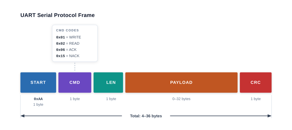
1.2. The Anatomy of the Frame
 ┌──────┬──────┬──────┬───────────┬───────┐
 │ START│ CMD  │ LEN  │  PAYLOAD  │  CRC  │
 │ 0xAA │ 1 B  │ 1 B  │  N bytes  │ 1 B   │
 └──────┴──────┴──────┴───────────┴───────┘
    1      1      1       0..32        1    = 4..36 bytes total
1.2.1 Start Byte — 0xAA
- Role: tells the parser “a new frame starts here.”
- Why
0xAA? Alternating bit pattern (10101010) is easy to spot on a scope and unlikely to appear naturally in ASCII config data. - Trade-off: a byte-stuffing scheme isn’t used (yet). If
0xAAappears inside the payload, a naive parser could get confused. For bounded, length-prefixed frames this is fine — we trust the length field and CRC to reject false positives.
1.2.2 Command Byte
Encodes the verb of the message. Currently:
| Value | Name | Direction | Meaning |
|---|---|---|---|
0x01 | CFG_CMD_WRITE | Master → Sensor | Write config registers |
0x02 | CFG_CMD_READ | Master → Sensor | Read back config |
0x06 | CFG_ACK | Sensor → Master | Success response |
0x15 | CFG_NACK | Sensor → Master | Failure response |
Important subtlety: ACK/NACK are single bytes, not framed. That’s a deliberate simplification — they carry no data, only status. When you extend to CMD_READ, the response will be a full frame (because it carries data).
1.2.3 Length Field
- One byte = max 255 bytes of payload, but we cap at
CFG_MAX_PAYLOAD = 32. - Why cap at 32? Keeps the DMA RX buffer small, bounded, and cache-friendly on the STM32F4.
- Why is length redundant with DMA’s
Size? BecauseSizereflects how many bytes the UART saw, not how many belong to this frame. If the master sends garbage first, the length field is the only reliable boundary. Belt and suspenders.
1.2.4 Payload
- Variable-size, up to
CFG_MAX_PAYLOAD. - Currently the payload for
CMD_WRITEis[sample_rate, threshold]— 2 bytes. - Design principle: the meaning of payload bytes is entirely determined by the command byte. This means one command can carry multiple different data layouts without changing the frame structure.
1.2.5 Checksum — XOR
crc = buf[0] ^ buf[1] ^ ... ^ buf[3+N-1]
The CRC byte is placed after the payload and covers everything from START through the last payload byte.
Properties of XOR:
- Detects: any single-byte error, any odd number of bit errors in the frame.
- Misses: an even number of bit errors that cancel out. E.g., flipping bit 3 of byte 2 and bit 3 of byte 5 produces the same XOR.
- Cost: 1 byte, ~N cycles, trivial to implement.
When to upgrade to CRC-16:
- Once you start streaming sensor data at high rates.
- When a corrupted-but-valid frame would cause a safety or calibration issue.
- When frames exceed ~16 bytes (XOR’s miss probability rises with size).
CRC-16/CCITT costs ~2× the bytes and ~50× the cycles but is standard practice. For configuration frames, XOR is fine.
1.3. The Parsing State Machine
Even though the current parser is “stateless” (it examines a complete buffer), it helps to think of it as a state machine. This is what you’d implement later if you move to byte-by-byte parsing:
       ┌─────────────┐
       │  WAIT_START │◄────────────┐
       └──────┬──────┘             │
              │ byte == 0xAA       │
              ▼                    │
       ┌─────────────┐             │
       │  WAIT_CMD   │             │
       └──────┬──────┘             │
              │                    │
              ▼                    │
       ┌─────────────┐             │
       │  WAIT_LEN   │             │
       └──────┬──────┘             │
              │                    │
              ▼                    │
       ┌─────────────┐             │
       │ WAIT_PAYLOAD│             │
       └──────┬──────┘             │
              │ N bytes received   │
              ▼                    │
       ┌─────────────┐             │
       │ WAIT_CRC    │             │
       └──────┬──────┘             │
              │ CRC ok → process   │
              │ CRC bad → NACK ────┘
              │
              ▼
           process(cmd, payload)
Why this matters: the current DMA+IDLE approach gives you whole chunks of bytes at a time. If the master sends a partial frame (e.g., due to a buffer glitch), the current parser rejects it — but a state machine would wait for the rest. For a config protocol where frames are short and infrequent, the simple buffer-based parser is the right choice.
1.4. Error Handling: What Happens When Things Go Wrong?
There are six ways a frame can be rejected, each mapping to a cfg_status_t:
| Error | Cause | Response |
|---|---|---|
CFG_ERR_TOO_SHORT | Fewer than 4 bytes | NACK |
CFG_ERR_BAD_START | First byte ≠ 0xAA | NACK |
CFG_ERR_TOO_LONG | Length > CFG_MAX_PAYLOAD | NACK |
CFG_ERR_BAD_CRC | Checksum mismatch | NACK |
CFG_ERR_UNKNOWN_CMD | Command not recognized | NACK |
CFG_ERR_BAD_PAYLOAD | Payload size wrong for command | NACK |
Design decision: should we distinguish these on the wire? Currently no — all errors return 0x15. That’s a simplification that trades debuggability for a smaller command set.
When to add error codes: once you have multiple failure modes that need different recovery actions on the master (e.g., “CRC error → retry” vs. “unknown command → don’t retry”). Then you’d extend NACK into a full frame: [0xAA, 0x15, 0x01, error_code, CRC].
1.5. Timing & Flow Control
Right now there is none, and that’s actually OK for configuration.
Why?
- Config frames are small (≤ 36 bytes) and infrequent (once per boot, or on demand).
- The emulator replies with a single byte (ACK/NACK) — near-instant.
- The master sends its next frame only after
HAL_Delay(500).
What would force you to add flow control:
- Multi-frame configs (e.g., a 100-byte calibration table split across frames).
- Simultaneous reads and writes.
- If the sensor ever produces data on its own (streaming mode), you’d need to interleave config commands with data frames — which is where a proper master/slave polling model like Modbus comes in.
1.6. Protocol Extension Paths
Here are the natural next steps, in order of increasing complexity:
1.6.1 Read-Back (Easy)
Extend CMD_READ so the emulator builds a response frame:
Master → Sensor:  0xAA 0x02 0x00 CRC
Sensor → Master:  0xAA 0x82 0x02 [rate] [thr] CRC
Note 0x82 = 0x02 | 0x80 — the high bit marks “response” so the same command code is reused.
1.6.2 Register Addressing (Medium)
Payload becomes [addr, value] for writes and [addr] for reads:
CMD_WRITE payload = [0x00, 20]    // write 20 to register 0 (sample_rate)
CMD_WRITE payload = [0x01, 75]    // write 75 to register 1 (threshold)
This decouples the protocol from the specific config layout — you can add registers without changing the frame.
1.6.3 Multi-Write (Medium)
Payload = [addr0, val0, addr1, val1, ...] — one frame configures everything.
1.6.4 CRC-16 (Medium)
Replace XOR with CRC-16/CCITT and expand CRC field to 2 bytes.
1.6.5 Sequence Numbers (Harder)
Add a seq byte so the master can match responses and detect dropped frames:
[START, CMD, SEQ, LEN, PAYLOAD..., CRC]
1.6.6 Modbus RTU (Full)
At that point you’re essentially reimplementing Modbus RTU. If your target sensor uses Modbus, just use Modbus — don’t reinvent it. The frame format you have now is a good mental stepping stone toward it.
1.7. Design Rules Worth Internalizing
- START + LEN + CRC is the minimum viable frame. Without all three, you’re gambling.
- The command byte owns the payload semantics. Never let payload interpretation depend on anything else.
- ACK/NACK as single bytes is fine for config. Don’t over-engineer until you have a reason.
- Reserve the high bit of the command byte for “this is a response” — you’ll thank yourself later.
- Cap payload length in the header, not in the parser.
CFG_MAX_PAYLOADshould be a compile-time constant shared by both sides. - Bytes are big-endian unless you decide otherwise. For config data it rarely matters, but pick a convention now. This protocol is endian-agnostic because all fields are 1 byte — keep it that way as long as possible.
- XOR checksum until you have a reason for CRC-16. Reason = streaming data, or fields where a corrupted-but-valid frame causes harm.
- Test the parser in isolation. Write a host-side C test that feeds it random byte sequences and confirms it never crashes. STM32 debugging is slow; PC debugging is fast.
2. Protocol Development:
Open both, the emulated sensor and master projects.
We start by creating new header and source file with name of config_protocol.h and config_protocol.h respectively.
To create the header file, right click on inc folder, and select new, header file as follows:
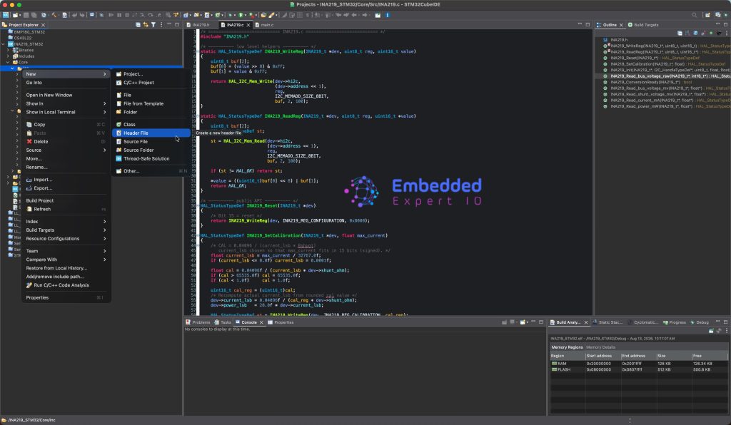
Give it a name config_protocol.h and click on Finish.
To create new source file, right click on src folder, new and Source file as follows:

Give it a name config_protocol.c and click on Finish.
Next, in the header:
Include both stdint and stdbool header files:
#include <stdint.h>
#include <stdbool.h>
Declare the frame constant:
/* ---- Frame constants ---- */
#define CFG_START_BYTE      0xAA
#define CFG_CMD_WRITE       0x01
#define CFG_CMD_READ        0x02
#define CFG_ACK             0x06
#define CFG_NACK            0x15
#define CFG_MAX_PAYLOAD     32
Total frame size:
/* Total frame = START(1) + CMD(1) + LEN(1) + PAYLOAD(N) + CRC(1) */
#define CFG_FRAME_OVERHEAD  4
#define CFG_MAX_FRAME       (CFG_MAX_PAYLOAD + CFG_FRAME_OVERHEAD)
Next, Results code:
/* ---- Result codes ---- */
typedef enum {
    CFG_OK = 0,
    CFG_ERR_TOO_SHORT,
    CFG_ERR_BAD_START,
    CFG_ERR_TOO_LONG,
    CFG_ERR_BAD_CRC,
    CFG_ERR_UNKNOWN_CMD,
    CFG_ERR_BAD_PAYLOAD
} cfg_status_t;
Parsed Frame view:
/* ---- Parsed frame view ---- */
typedef struct {
    uint8_t  cmd;
    uint8_t  length;
    uint8_t  payload[CFG_MAX_PAYLOAD];
} cfg_frame_t;
Next, checksum function:
uint8_t cfg_checksum(const uint8_t *data, uint16_t len);
Next, frame builder:
uint16_t cfg_build_frame(uint8_t *out,
                         uint8_t cmd,
                         const uint8_t *payload,
                         uint8_t payload_len);
Finally, frame parser:
cfg_status_t cfg_parse_frame(const uint8_t *buf,
                             uint16_t size,
                             cfg_frame_t *frame);
Hence, the header file as follows:
#ifndef INC_CONFIG_PROTOCOL_H_
#define INC_CONFIG_PROTOCOL_H_

#include <stdint.h>
#include <stdbool.h>

/* ---- Frame constants ---- */
#define CFG_START_BYTE      0xAA
#define CFG_CMD_WRITE       0x01
#define CFG_CMD_READ        0x02
#define CFG_ACK             0x06
#define CFG_NACK            0x15
#define CFG_MAX_PAYLOAD     32

/* Total frame = START(1) + CMD(1) + LEN(1) + PAYLOAD(N) + CRC(1) */
#define CFG_FRAME_OVERHEAD  4
#define CFG_MAX_FRAME       (CFG_MAX_PAYLOAD + CFG_FRAME_OVERHEAD)

/* ---- Result codes ---- */
typedef enum {
    CFG_OK = 0,
    CFG_ERR_TOO_SHORT,
    CFG_ERR_BAD_START,
    CFG_ERR_TOO_LONG,
    CFG_ERR_BAD_CRC,
    CFG_ERR_UNKNOWN_CMD,
    CFG_ERR_BAD_PAYLOAD
} cfg_status_t;

/* ---- Parsed frame view ---- */
typedef struct {
    uint8_t  cmd;
    uint8_t  length;
    uint8_t  payload[CFG_MAX_PAYLOAD];
} cfg_frame_t;

/* ---- Checksum ---- */
uint8_t cfg_checksum(const uint8_t *data, uint16_t len);

/* ---- Frame builder: returns total bytes written (0 on error) ---- */
uint16_t cfg_build_frame(uint8_t *out,
                         uint8_t cmd,
                         const uint8_t *payload,
                         uint8_t payload_len);

/* ---- Frame parser: fills `frame` on success ---- */
cfg_status_t cfg_parse_frame(const uint8_t *buf,
                             uint16_t size,
                             cfg_frame_t *frame);
Next, in config_protocol.c source file:
Include the following header file:
#include "config_protocol.h"
#include <string.h>
Next, the check sum function:
uint8_t cfg_checksum(const uint8_t *data, uint16_t len)
{
    uint8_t crc = 0;
    for (uint16_t i = 0; i < len; i++) {
        crc ^= data[i];
    }
    return crc;
Next, build frame function:
uint16_t cfg_build_frame(uint8_t *out,
                         uint8_t cmd,
                         const uint8_t *payload,
                         uint8_t payload_len)
{
    if (out == NULL) return 0;
    if (payload_len > CFG_MAX_PAYLOAD) return 0;
    if ((payload_len > 0) && (payload == NULL)) return 0;

    uint16_t idx = 0;
    out[idx++] = CFG_START_BYTE;
    out[idx++] = cmd;
    out[idx++] = payload_len;

    for (uint8_t i = 0; i < payload_len; i++) {
        out[idx++] = payload[i];
    }

    out[idx] = cfg_checksum(out, idx);
    idx++;

    return idx;
}
Finally, parse frame:
cfg_status_t cfg_parse_frame(const uint8_t *buf,
                             uint16_t size,
                             cfg_frame_t *frame)
{
    if ((buf == NULL) || (frame == NULL)) return CFG_ERR_TOO_SHORT;
    if (size < CFG_FRAME_OVERHEAD)       return CFG_ERR_TOO_SHORT;
    if (buf[0] != CFG_START_BYTE)        return CFG_ERR_BAD_START;

    uint8_t cmd     = buf[1];
    uint8_t payload = buf[2];

    if (payload > CFG_MAX_PAYLOAD)       return CFG_ERR_TOO_LONG;
    if (size < (uint16_t)(payload + CFG_FRAME_OVERHEAD))
                                         return CFG_ERR_TOO_SHORT;

    /* Checksum covers START..last payload byte */
    uint8_t expected = cfg_checksum(buf, (uint16_t)(payload + 3));
    if (expected != buf[3 + payload])    return CFG_ERR_BAD_CRC;

    frame->cmd    = cmd;
    frame->length = payload;
    if (payload > 0) {
        memcpy(frame->payload, &buf[3], payload);
    }
    return CFG_OK;
}
Thats all for the protocol.
Next part will focus on implementing the sensor configuration on emulated MCU.
Stay tuned.
Happy coding 😉

Add Comment