
Accurate timing is a fundamental requirement in most embedded applications, whether for blinking an LED, polling a sensor, or driving communication protocols. This guide shows how to turn TIM2 into a simple, reliable millisecond delay function using the STM32 Low-Layer (LL) API—a lightweight, cycle-accurate alternative to busy-wait software loops.
In this guide, we shall cover the following:
- Introduction.
- STM32CubeMX setup.
- Importing the project to STM32CubeMX.
- Firmware Development.
- Results.
1. Introduction:
Timing is the invisible thread that runs through every embedded application. Whether you are blinking an LED, waiting for a sensor to complete a conversion, pacing an SPI transaction, or debouncing a mechanical switch, your firmware constantly has to answer one deceptively simple question: how do I wait for an exact amount of time?
Most beginners reach for the first answer that comes to mind — the empty software loop:
for (volatile uint32_t i = 0; i < 100000; i++);
It feels harmless, and it even appears to work — until it doesn’t. The real duration of such a loop depends on the compiler optimization level, the CPU clock frequency, flash wait states, and even the interrupt load at runtime. Recompile the same code from -O0 to -O2, and your carefully tuned 10 ms delay silently shrinks to 3 ms. Meanwhile, the CPU spends 100% of its cycles doing absolutely nothing useful. A software loop doesn’t measure time; it merely estimates it, and the estimate is only as good as the assumptions behind it.
The next step up is HAL_Delay(). It is at least anchored to a real time base (SysTick), but it comes with its own caveats: it silently freezes if it is called while interrupts are disabled, it can deadlock when called from within an interrupt of higher priority, and it drags the entire HAL clock infrastructure along with it. For a simple delay, that is a lot of machinery to depend on.
There is a better tool, and it has been sitting on the chip the whole time: a hardware timer. Every STM32 microcontroller includes a set of independent, 16- or 32-bit timers that count with crystal-level precision, are completely unaffected by compiler settings, and require nothing more than a few register accesses to operate. No callbacks, no interrupt handlers, no framework — just a peripheral doing exactly what it was designed to do.
In this guide, we will build a precise, blocking millisecond delay function on TIM2 using STM32CubeMX and the Low-Layer (LL) API. The idea is simple and elegant: we configure the prescaler so the counter ticks at exactly 1 kHz — one tick per millisecond — then let the counter count down from our desired delay to zero. To wait, we simply poll the update flag and go on with our lives. Choosing the LL drivers is deliberate: they map almost one-to-one onto the timer’s registers, compile down to a handful of instructions, and — most importantly — teach you what is actuallyhappening inside the peripheral instead of hiding it behind layers of abstraction.
Along the way, you will learn:
- How the prescaler (PSC) and auto-reload register (ARR) work together to shape timing,
- Why
PSC = 16000 - 1turns a 16 MHz clock into exactly 1 ms per tick, - How down-counting works and why the update event fires on underflow,
- Why an explicit update event is required on the first call (the shadow-register gotcha that trips up almost everyone),
- How to assemble all of this into a compact, reusable delay function you can drop into any project.
2. STM32CubeMX Setup:
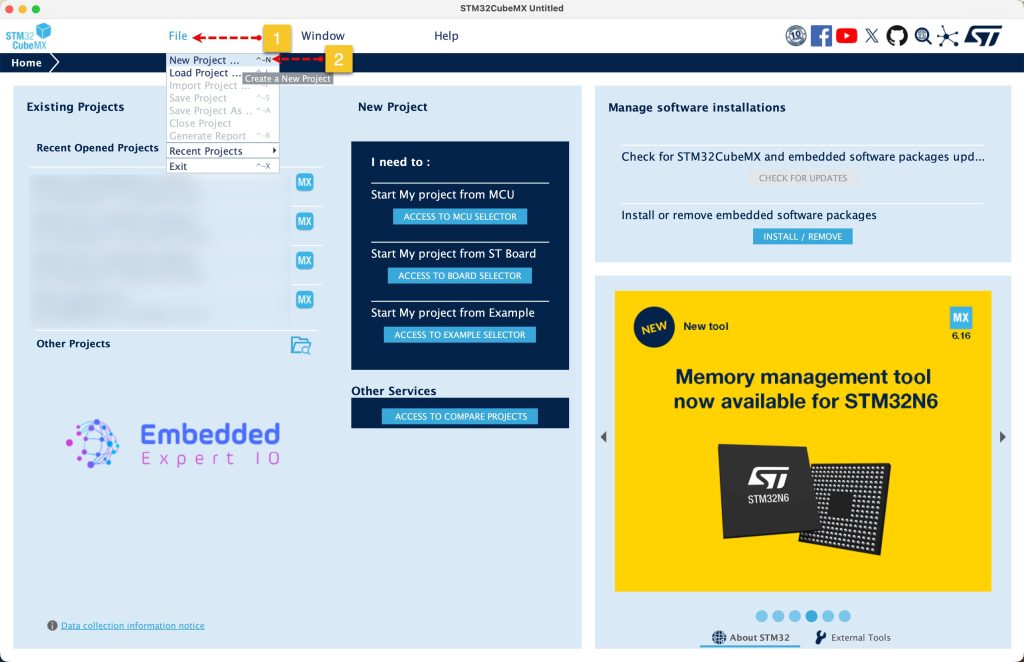
Open STM32CubeMX as start a new project as follows:
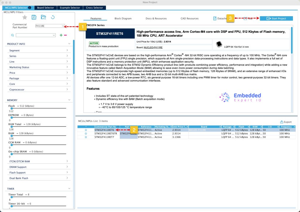
Search for your STM32 MCU, select the MCU and click on Start New Project as follows:
Next, from Timer, select TIM2:
- Set Clock source to Internal Clock.
- Set the PSC (prescaler to 16000-1)
- Set the Counter Mode to Down.
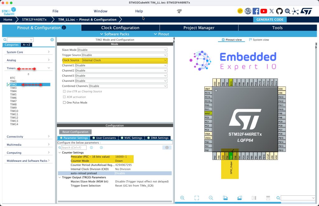
Next, set PA5 as output.
Next, from project manager, Advanced Settings, set both TIM and GPIO as LL as follows:
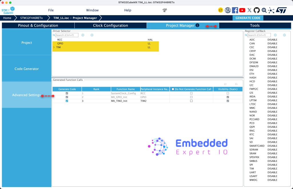
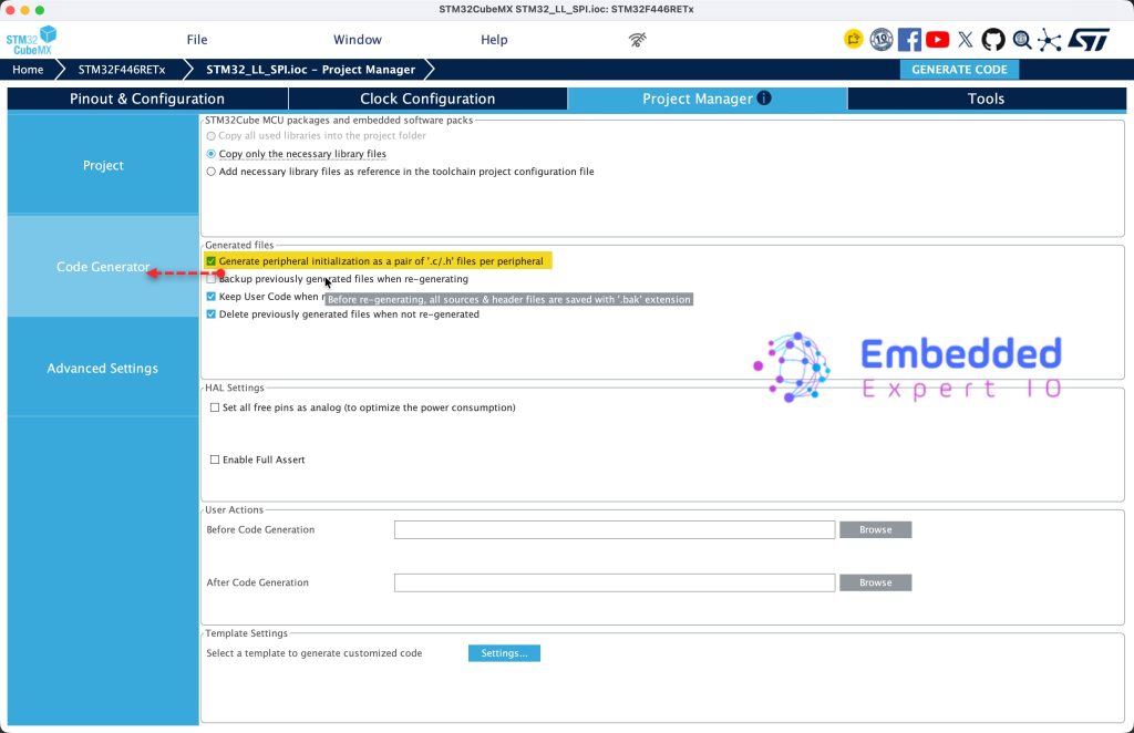
Next, from Code Generator, enable Create peripheral initialization as pair of .c/.h files per peripheral as follows:
Next, from Project, give the project a name and set toolchain/IDE to STM32CubeIDE and click on Generate Code as follows:
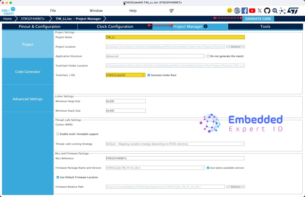
Thats all for the STM32CubeMX setup.
3. Importing the Project to STM32CubeIDE:
Open STM32CubeIDE, select your workspace and click on Launch.
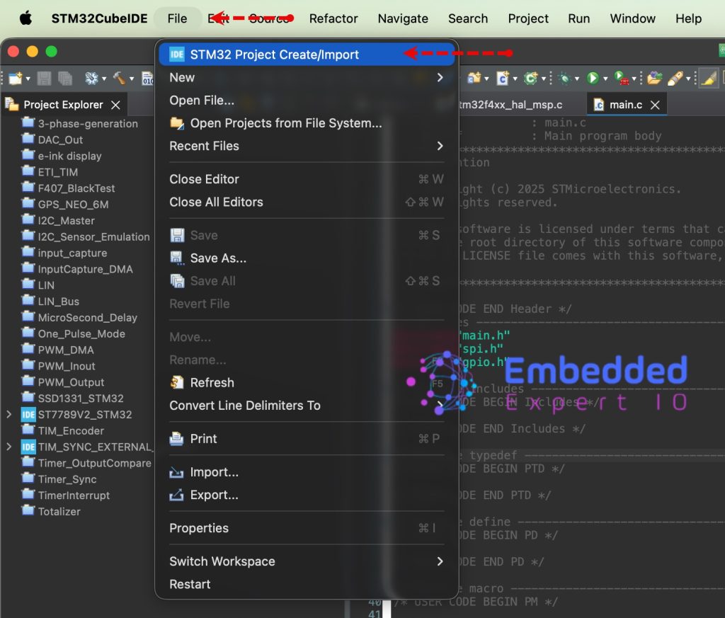
From the IDE, click File and select STM32 Project Create/Import as follows:
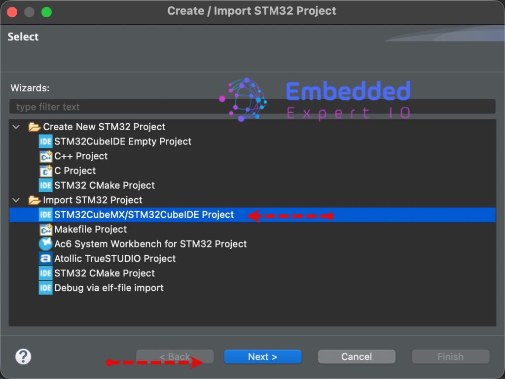
Next, from Import STM32 Project, select STM32CubeMX/STM32CubeIDE Project and click on Next as follows:
Next, select the folder that contains the .ioc file and click on Finish as follows:
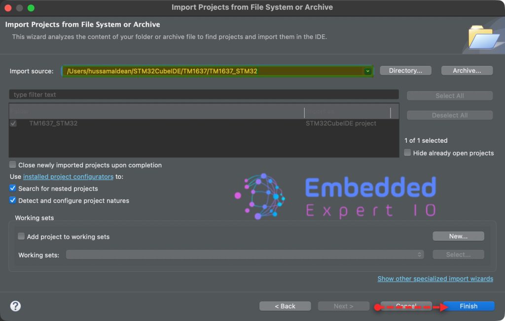
Note: Project name is for reference only.
4. Firmware Development:
Open tim.h.
In USER CODE BEGIN Prototypes, declare the following function:
void TIM_Delay_ms(TIM_TypeDef *TIMx, uint32_t ms);
This function shall block delay for certain amount of time in milli seconds.
The function takes the following parameters:
- Typedef for which timer, TIM2 in this guide.
- The amount to be delayed in milliseconds.
Next, open tim.c
In USER CODE BEGIN 1, declare the following function:
void TIM_Delay_ms(TIM_TypeDef *TIMx, uint32_t ms)
Within the function, disable the timer:
LL_TIM_DisableCounter(TIMx);
Set the ARR (Auto Reload Register) to the desired delay amount.
LL_TIM_SetAutoReload(TIMx, ms);
Generate the event update flag and clear the flag:
//	// Force an update event so ARR is loaded into the active register
//	// and CNT is reloaded with ARR (down-count mode)
LL_TIM_GenerateEvent_UPDATE(TIMx);
//
LL_TIM_ClearFlag_UPDATE(TIMx);
Next, enable the timer:
LL_TIM_EnableCounter(TIMx);
Wait for the update flag to set:
while (!LL_TIM_IsActiveFlag_UPDATE(TIMx))
{
  // Blocking wait
}
Finally, clear the update flag the stop the timer:
// Stop the timer and clear the flag
LL_TIM_DisableCounter(TIMx);
LL_TIM_ClearFlag_UPDATE(TIMx);
Hence, the entire function:
void TIM_Delay_ms(TIM_TypeDef *TIMx, uint32_t ms)
{

	LL_TIM_DisableCounter(TIMx);

	LL_TIM_SetAutoReload(TIMx, ms);

//	// Force an update event so ARR is loaded into the active register
//	// and CNT is reloaded with ARR (down-count mode)
	LL_TIM_GenerateEvent_UPDATE(TIMx);
//
	LL_TIM_ClearFlag_UPDATE(TIMx);

	LL_TIM_EnableCounter(TIMx);

	while (!LL_TIM_IsActiveFlag_UPDATE(TIMx))
	{
		// Blocking wait
	}

	// Stop the timer and clear the flag
	LL_TIM_DisableCounter(TIMx);
	LL_TIM_ClearFlag_UPDATE(TIMx);
}
In main.c:
In user code begin 3 in while 1 loop:
LL_GPIO_TogglePin(GPIOA, LL_GPIO_PIN_5);
TIM_Delay_ms(TIM2,1000);
Toggle pin PA5 and wait for 1 seconds (1000ms)
Thats all for the firmware.
Save, build and run the project on your board.

You may download the project from here.
5. Results:
You should get the following
Later, we shall build on this to develop more timer applications.
Stay tuned.
Happy coding 😉

Add Comment