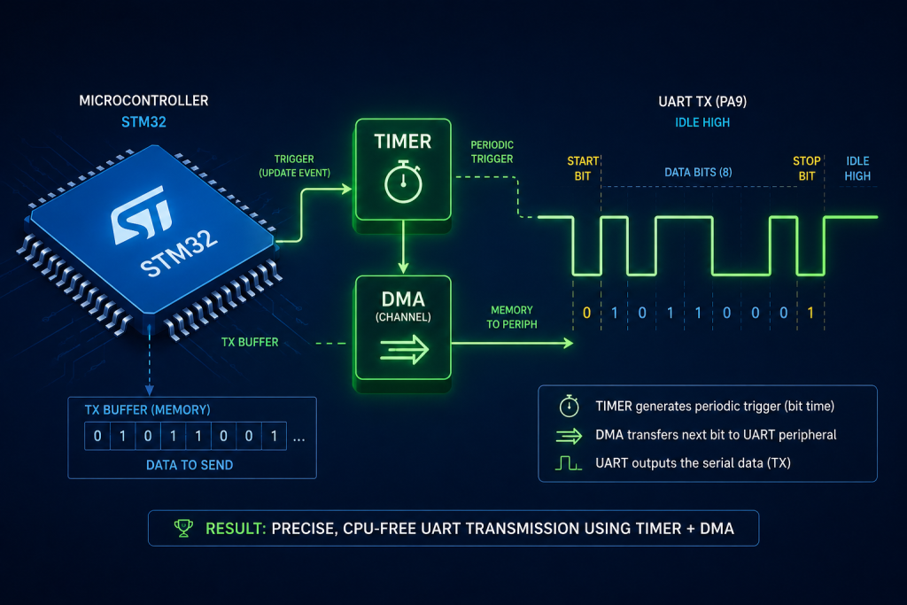
In this new series guide, we shall emulate the UART hardware using a clever combination of timers and DMA to achieve effortless, CPU-independent serial communication. Before a single byte can take flight, we will use STM32CubeMX to forge the precise timing pathways and autonomous logic required to bring this invisible engine to life.
In this guide, we shall cover the following:
- Introduction.
- How to calculate the baudrate
- STM32CubeMX setup.
- Importing the project to STM32CubeIDE.
1. Introduction:
Why Software Emulation?
As your project grows, you often find yourself running out of available hardware UART ports. You might need just one more debug log, a connection to a specialized sensor, or an extra serial channel on a pin that lacks a hardware transceiver. Software UART bridges this gap, allowing you to turn any standard GPIO into a fully functional serial port. It provides the ultimate flexibility to expand your microcontroller’s communication capabilities beyond its physical limitations.
How Does Soft UART Work?
A standard UART frame is simply a timed sequence of high and low voltage pulses—a start bit, eight data bits, and a stop bit. Traditional software UART implementations force the CPU to manually toggle a pin and waste cycles in blocking delay loops to time the bits. Our approach is far more elegant: we use a hardware timer configured in “Output Compare Toggle” mode. By pre-calculating the exact moments the signal needs to change state and feeding those timestamps via DMA directly to the timer, the microcontroller’s hardware autonomously generates the perfect UART waveform. The CPU is completely uninvolved.
Advantages and Disadvantages
The Good:
- CPU Independence: Because DMA handles the heavy lifting, your CPU is 100% free to execute critical code while bytes transmit seamlessly in the background.
- Pin Flexibility: You are no longer bound by fixed alternate-function pins. Any GPIO can become a TX line.
- Total Customization: You can easily tweak the code for inverted logic, custom baud rates, or non-standard frame sizes (like 7 or 9 data bits).
The Trade-offs:
- Resource Cost: This method consumes a hardware timer and a DMA stream, which might be scarce in complex, heavily loaded applications.
- Timing Jitter: While DMA is precise, it isn’t immune to bus contention. Very high baud rates (above 115200 or 230400) might start to show jitter if the DMA is blocked by higher-priority transfers, whereas a dedicated hardware UART is bulletproof.
- RX Complexity: Transmitting asynchronously via DMA is straightforward, but receiving is notoriously tricky. Capturing asynchronous incoming edges with timers and reconstructing the bytes requires careful state management and edge-case handling.
2. How to Calculate the Baudrate:
Here is a dedicated section explaining the math behind the timer configuration. You can add this right after the CubeMX setup steps or just before diving into the code.
Understanding the Math: Calculating Timer Parameters
To emulate a UART port reliably, the underlying timer must tick at a rate that allows us to slice the signal into exact “bit times.” If our timing is off by even a fraction of a percent, the receiving device will misinterpret the 1s and 0s.
Here is how we calculate the timer parameters to achieve a target baud rate of 115200 on an STM32F411RE running at 100 MHz.
1. Determine the Timer Clock Frequency
On the STM32F411RE, we configured the system clock (SYSCLK) to 100 MHz.
Because the APB1 prescaler is set to 2, the APB1 peripheral clock is 50 MHz. However, by STM32 hardware design, if the APB prescaler is not 1, the timer clock is automatically doubled. Therefore, our TIM3 clock is exactly 100,000,000 Hz (100 MHz).
2. Calculate Ticks Per Bit
A baud rate of 115200 means 115,200 bits are transmitted every second. Therefore, the duration of a single bit is:

We need to figure out how many timer ticks fit into this 8.68uS window. The formula is:

For our setup:

Since timer registers can only hold whole integers, we must round. As recommended by ST’s AN4457, we use mathematical rounding (adding half the divisor before integer division) to minimize drift over the 10-bit UART frame:

3. Verify the Baud Rate Error
Because we rounded 868.055 down to 868, our actual baud rate will be slightly faster than 115200. Let’s calculate the error:

Standard UART communication can tolerate up to 2% to 3% error before bits start corrupting. Our error of 0.006% is virtually perfect.
4. Choosing the Prescaler (PSC) and Auto-Reload (ARR)
- Prescaler (PSC): Because 100MHz divided by 115200 gives us 868 (which easily fits inside a 16-bit register), we don’t need to slow the timer down. We set PSC = 0, meaning the timer ticks at the full 100 MHz.
- Auto-Reload (ARR): A standard UART frame is 10 bits long (1 Start + 8 Data + 1 Stop). The total ticks for a full frame is 10 times 868 = 8,680 ticks. We set ARR = 65535 (the maximum 16-bit value) so the timer counter never resets in the middle of a transmission.
3. STM32CubeMX Setup:
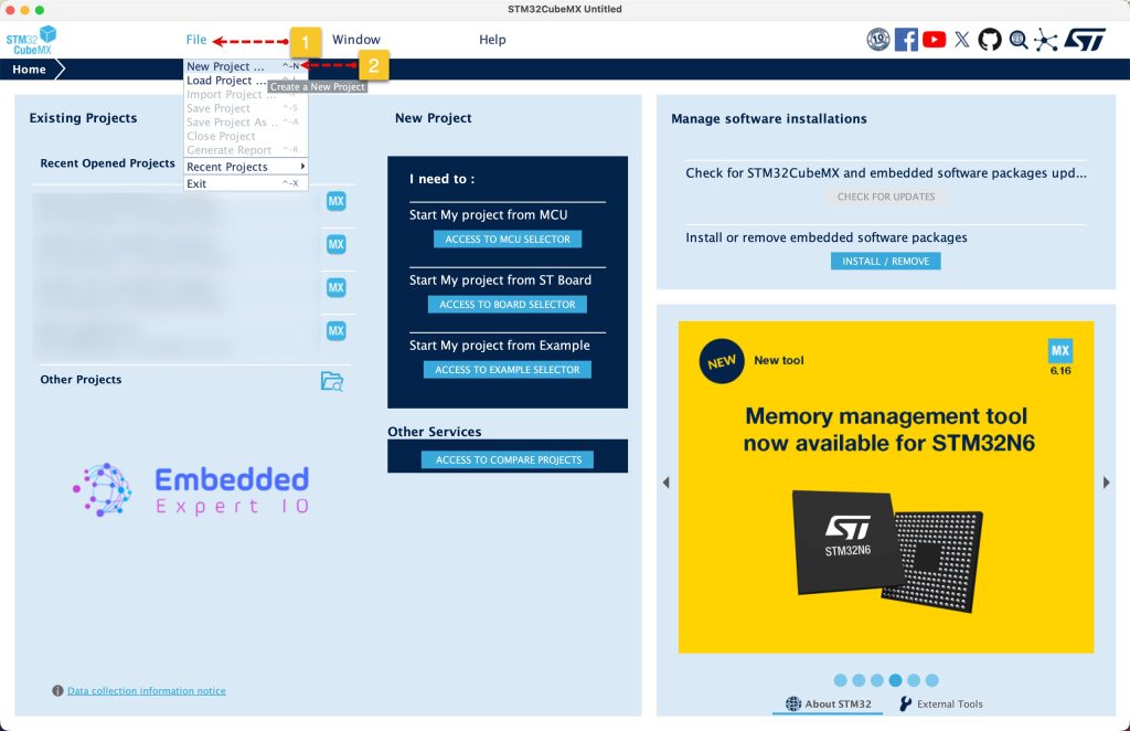
Open STM32CubeMX as start a new project as follows:
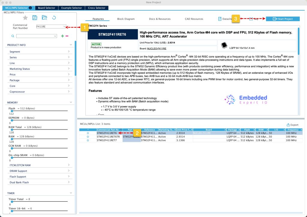
Search for your STM32 MCU, select the MCU and click on Start New Project as follows:
Next, from System Core RCC, enable the external oscillator:
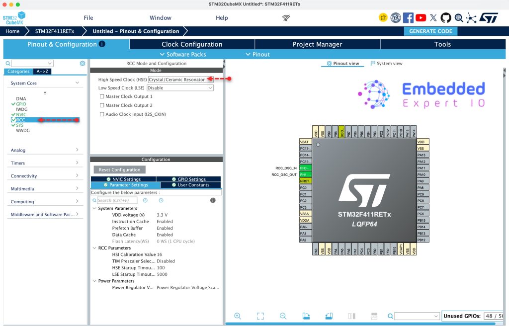
Since this guide shall use STM32F411RE Nucleo, it has 8MHz clock generated by on board ST-Link.
From Clock Configuration:
- Set Input Frequency to 8MHz.
- Set PLL source to HSE.
- Set HCLK to 100MHz and hit enter
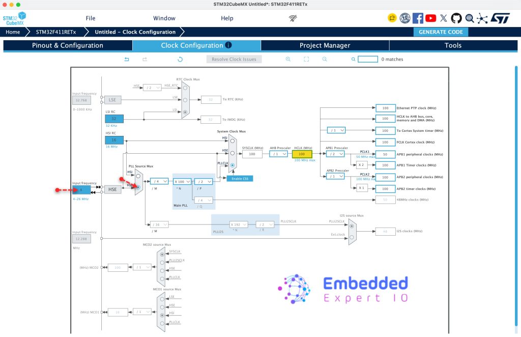
This will set the maximum frequency for the MCU. Please note that if your MCU can operate faster than 100MHz, you need to set it to 100MHz when you follow this guide.
Next, from Pinout and Configuration:
First, set PA6 to be GPIO output and name it soft_tx. This will be our TX pin
Next, from Timers, select TIM3, set the clock source to internal, set Counter Period to 868 which will be equivalent to 115200 for 100MHz timer. Also, enable auto-reload preload.
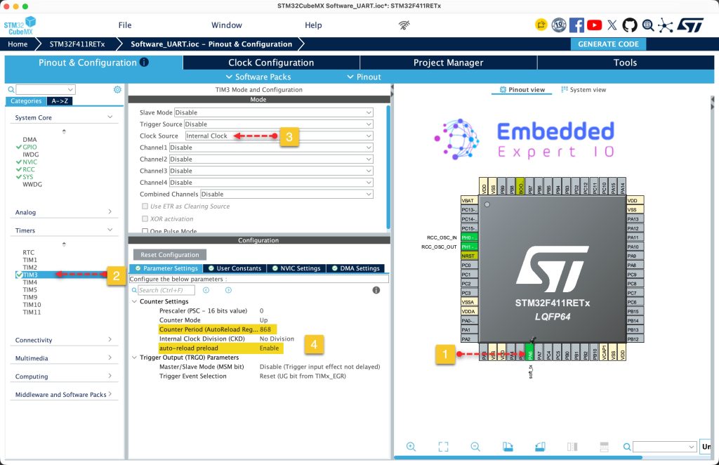
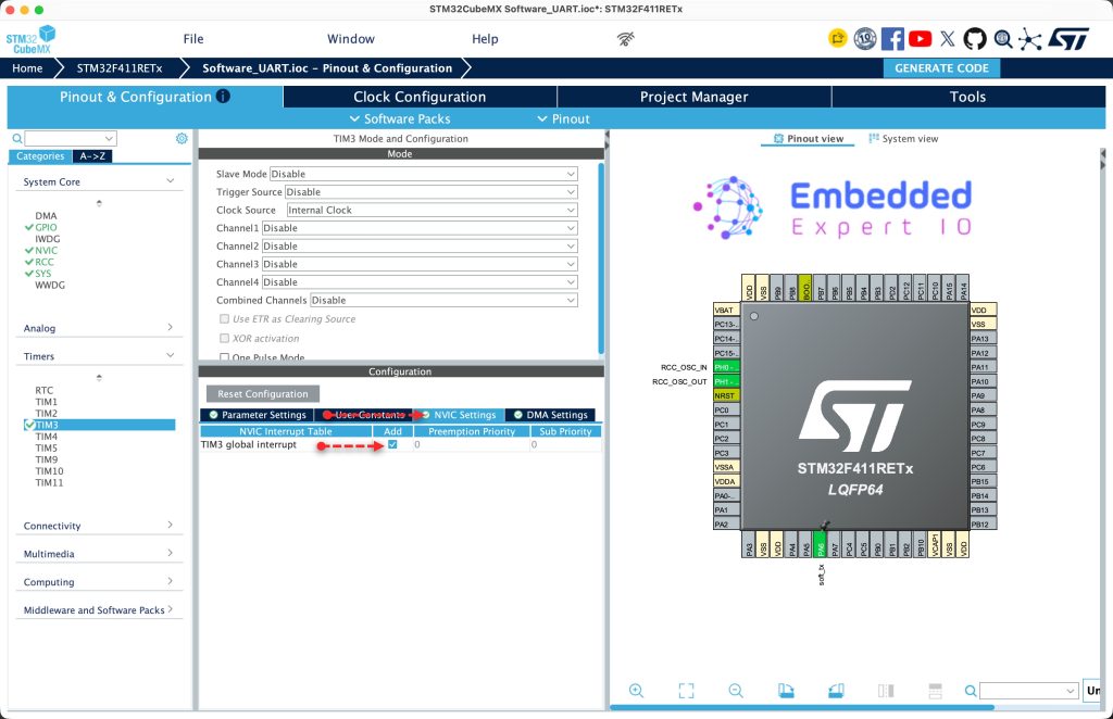
Next, for NVIC Settings, enable timer global interrupt as follows:
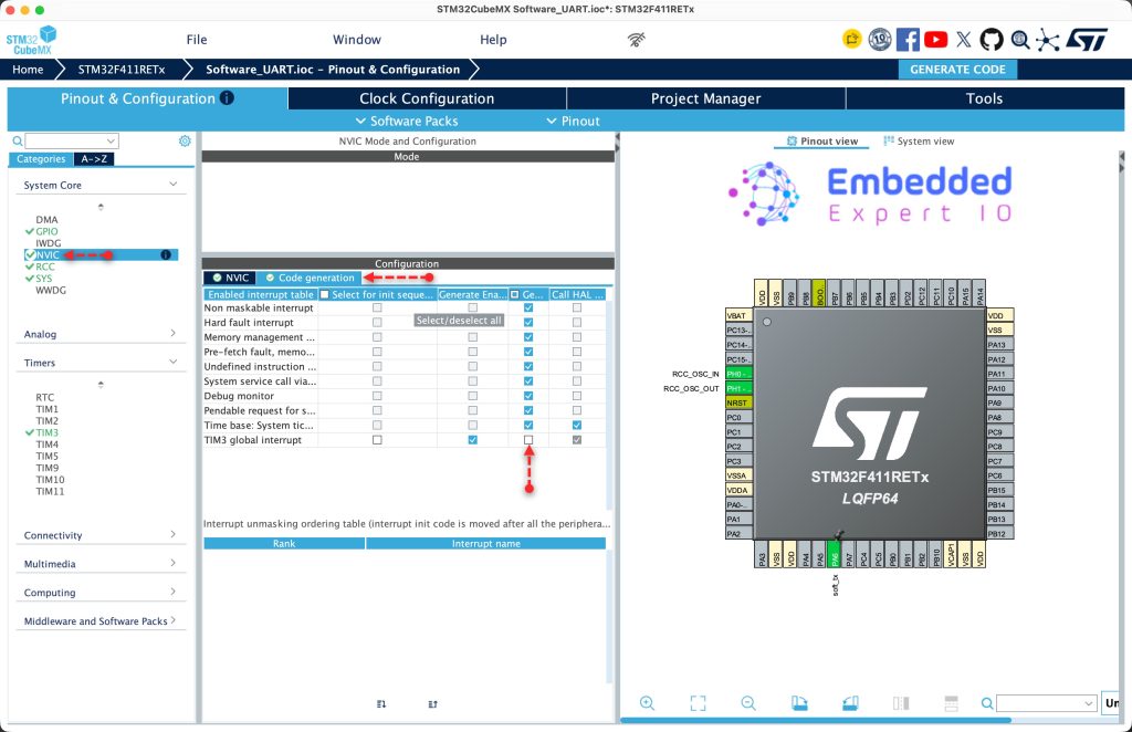
Next, from System Core, NVIC, go to Code Generation tab and disable generate IRQ handler for TIM3 as follows:
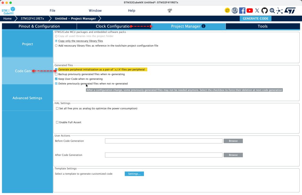
Next, from Project Manager, Code Generation, enable generate peripherals initialization as pair .c/.h files per peripheral.
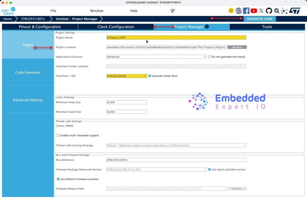
Finally, from Project, give the project a name, set the toolchain/IDE to STM32CubeIDE and click on generate code as follows:
4. Importing the Project to STM32CubeIDE:
Open STM32CubeIDE, select your workspace and click on Launch.
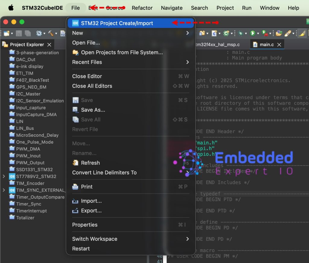
From the IDE, click File and select STM32 Project Create/Import as follows:
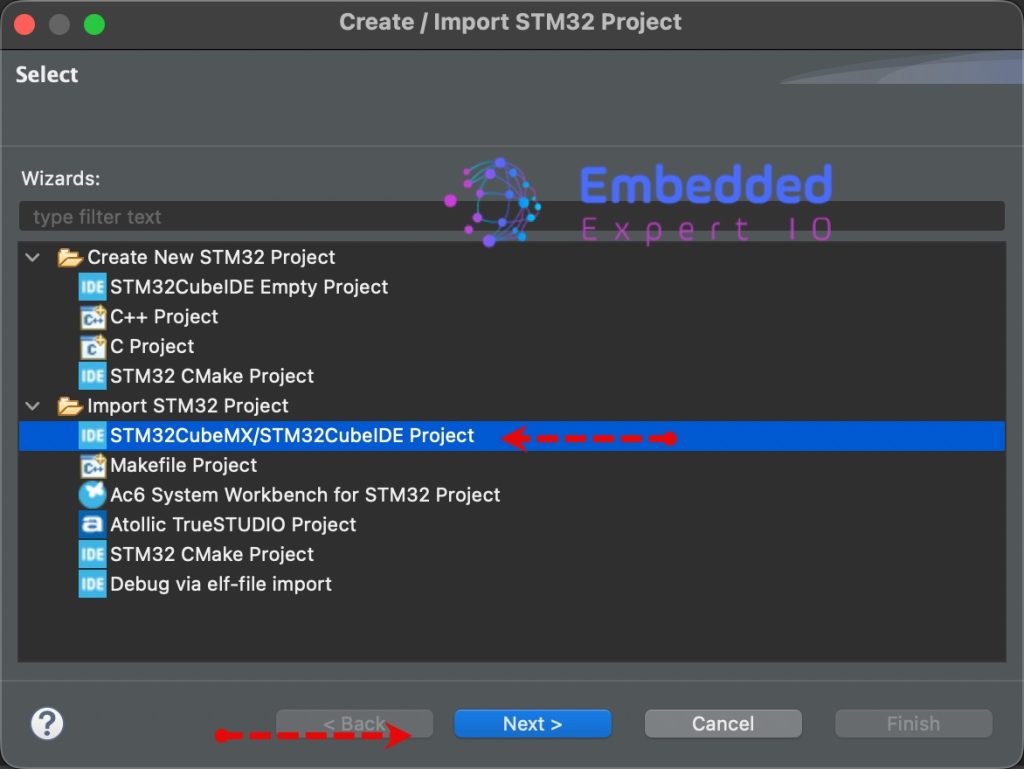
Next, from Import STM32 Project, select STM32CubeMX/STM32CubeIDE Project and click on Next as follows:
Next, select the folder that contains the .ioc file and click on Finish as follows:
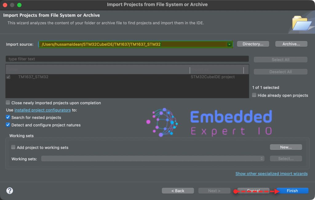
Note: Project name is for reference only.
In next part, we shall start developing the code to transmit data by software method.
Stay tuned.
Happy coding 😉

Add Comment