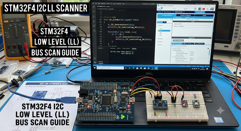
Mastering the I2C protocol at the register level offers unparalleled control and efficiency, especially when navigating the specialized Low-Layer (LL) drivers provided by ST. This first installment of our series walks you through the essential STM32CubeMX configuration and the development of a robust bus-scanning function to instantly identify connected peripherals.
In this guide, we shall cover the following:
- Introduction.
- Connection of slave device.
- STM32CubeMX setup.
- Importing the project to STM32CubeIDE.
- Firmware development.
- Results.
1. Introduction:
The Inter-Integrated Circuit (I2C) protocol is a synchronous, multi-master, multi-slave, packet-switched, single-ended, serial communication bus. Developed by Philips Semiconductors (now NXP) in 1982, it is widely used for attaching lower-speed peripheral ICs to processors and microcontrollers in short-distance, intra-board communication.
I2C relies on just two bidirectional lines pulled up by resistors:
- SDA (Serial Data Line): For data transfer.
- SCL (Serial Clock Line): For clock synchronization.
Because it only requires two pins regardless of how many devices are connected to the bus, it drastically reduces PCB complexity and pin-count requirements compared to parallel interfaces or SPI.
Applications of I2C
I2C is the industry standard for interacting with low-speed, low-power peripheral devices where wiring simplicity is prioritized over high-speed throughput. Common applications include:
- Sensor Interfacing: Reading data from environmental sensors (e.g., barometric pressure sensors like the BMP180/BMP280, temperature sensors, and IMUs).
- User Interface Components: Driving small alphanumeric or organic LED (OLED) screens, reading inputs from matrix keypads, or controlling IO expanders.
- Memory Modules: Reading and writing to small external non-volatile storage, such as EEPROMs (
24Cxxseries). - Real-Time Clocks (RTC): Keeping system time via chips like the DS3231 or DS1307.
- System Configuration & Monitoring: Reading hardware configuration data via Serial Presence Detect (SPD) in RAM modules, or managing battery metrics through Battery Management Systems (BMS).
HAL vs. LL Drivers in STM32
When programming I2C on STM32 microcontrollers, STMicroelectronics provides two distinct abstraction layers within the STM32Cube firmware package: Hardware Abstraction Layer (HAL) and Low-Layer (LL) drivers.
Choosing between them involves balancing ease of use against execution efficiency.
| Feature | Hardware Abstraction Layer (HAL) | Low-Layer (LL) Drivers |
| Abstraction Level | High: Hides register complexity behind abstract APIs (e.g., HAL_I2C_Master_Transmit). | Low: Directly maps to device registers using inline functions and macros. |
| Code Footprint | Large: Includes extensive state machines, safety checks, and overhead, leading to larger binary sizes. | Minimal: Generates highly optimized, lean machine code with almost no wrapper overhead. |
| Execution Speed | Slower: Internal state handling and blocking checks introduce latency. | Fast: Executes close to the hardware limits; ideal for time-critical, deterministic routines. |
| Ease of Use | High: Handles the complete I2C state machine (Start, Address, Data, Ack, Stop) automatically. | Moderate to Low: The developer must manually sequence every register step of the I2C protocol. |
| Portability | Excellent: Code is highly portable across different STM32 families with minimal modification. | Limited: Code is tightly coupled to the specific peripheral hardware implementation of the target MCU series. |
| Error Handling | Automated: Provides built-in error callbacks, timeouts, and automatic bus recovery attempts. | Manual: The programmer must explicitly poll status flags and handle bus errors or lockups in code. |
2. Connection of Slave Device:
Since the board used in this guide is STM32F411RE Nucleo-64.
The board features Arduino Uno pinout, D14 and D15 features I2C pins as shown below:
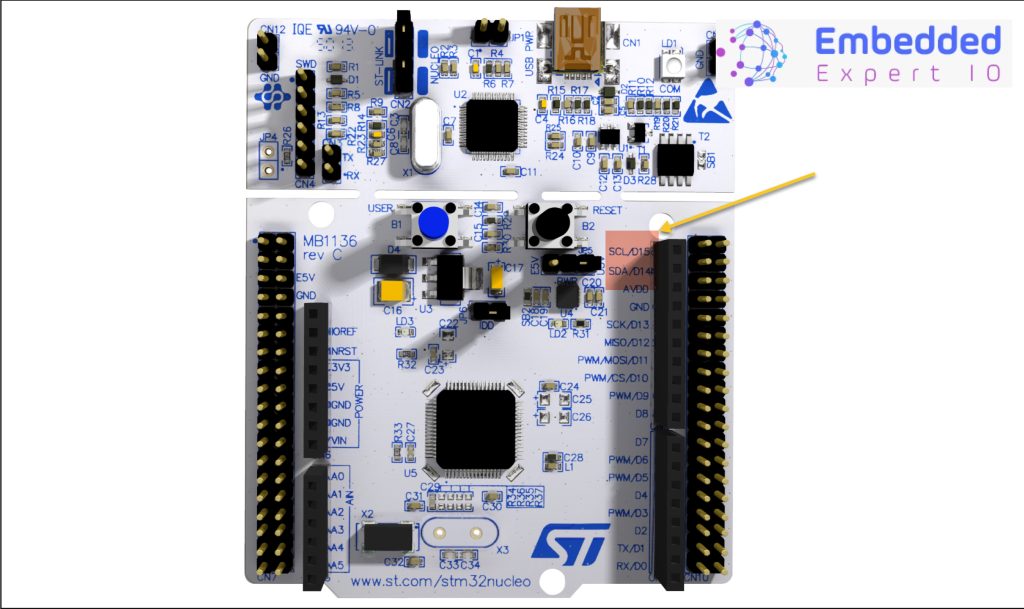
These pins can be found in the pinout in the user manual of STM32 Nucleo-64 boards (MB1136) as following:
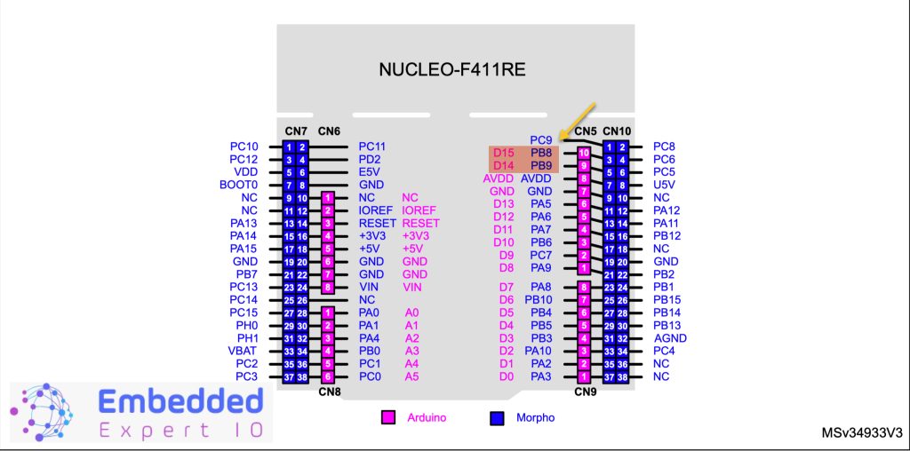
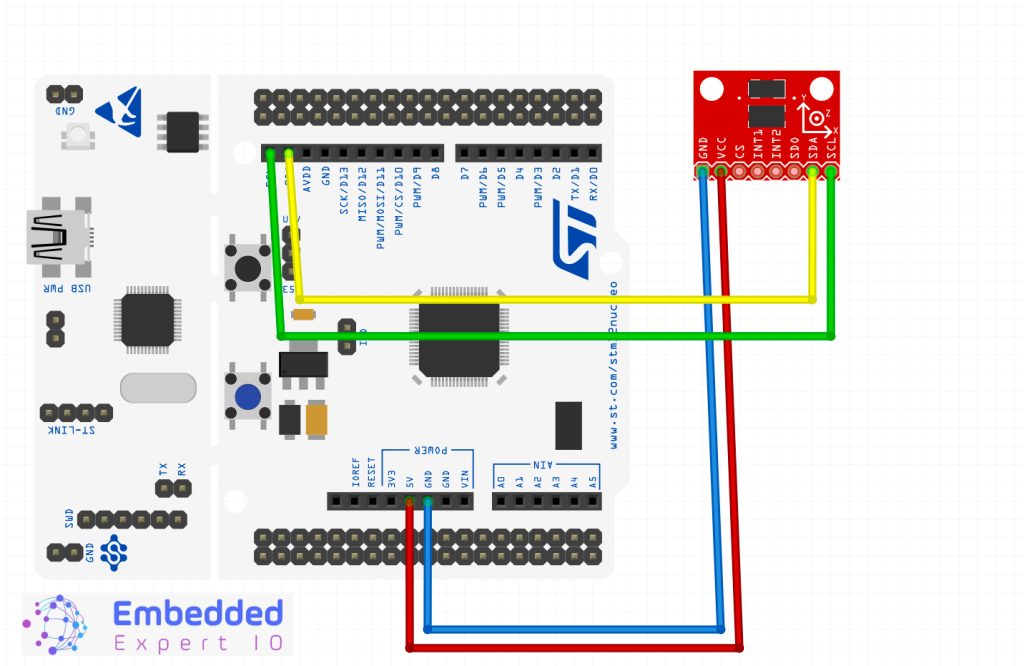
- PB8(D15) is SCL which is Serial Clock.
- PB9(D14) is SDA which is Serial Data.
Hence, the connection as following:
3. STM32CubeMX Setup:
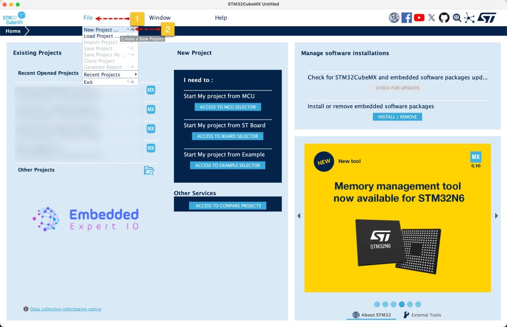
Open STM32CubeMX as start a new project as follows:
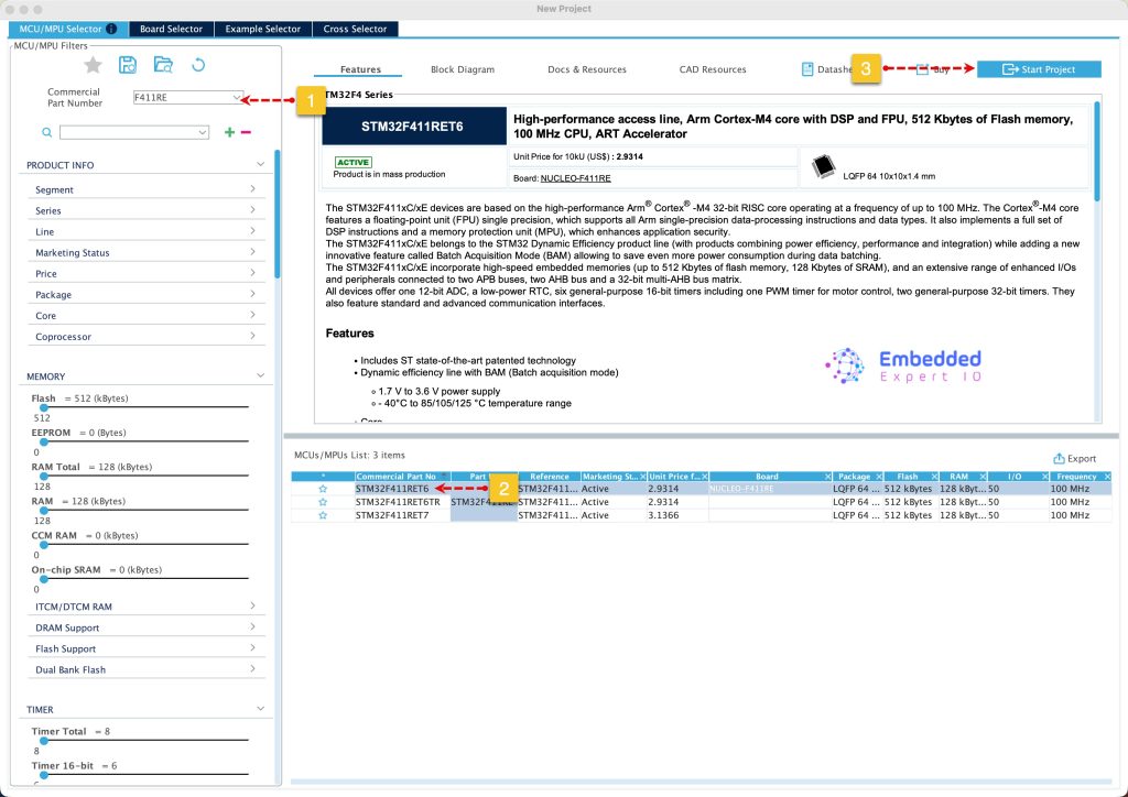
Search for your STM32 MCU, select the MCU and click on Start New Project as follows:
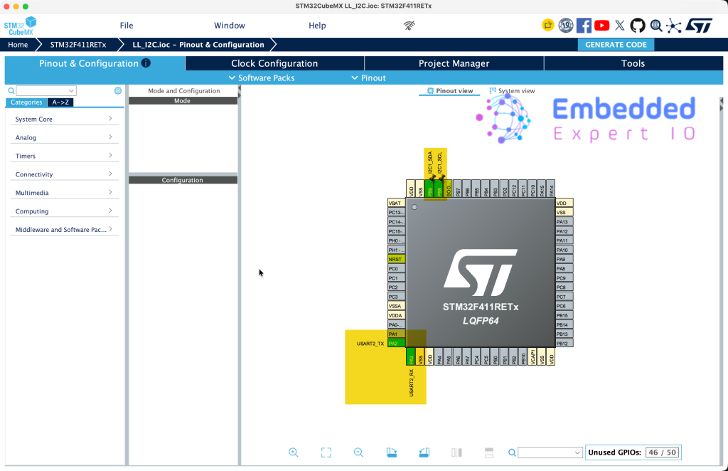
Next, set PB8 and PB9 for I2C bus also, PA2 and PA3 for UART to print data as follows:
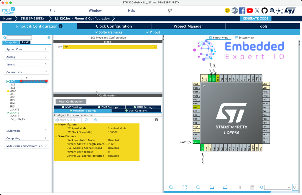
Configure I2C as follows:
- Set the mode to I2C.
- Keep the default configuration.
For detailed configuration of UART, please refer to this guide.
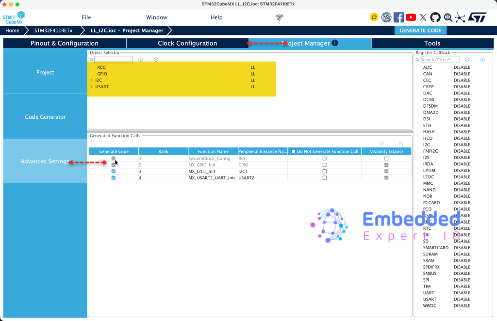
Next, from Project Manager, advanced settings, set the following:
- RCC to LL
- GPIO to LL
- I2C to LL
- USART to LL
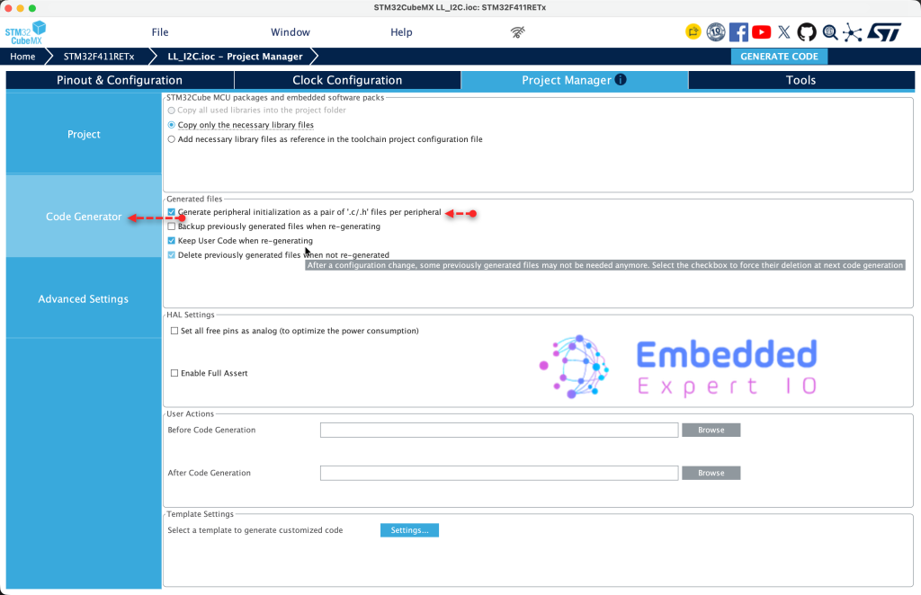
Next, from code generate, set generate peripheral initialization as pair of .c/.h files per peripheral as follows:
Next, from Project, give the project a name and set toolchain/IDE to STM32CubeIDE and click on Generate code as follows:
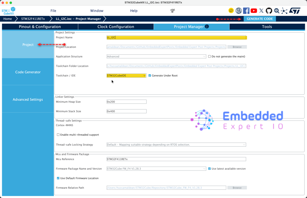
Thats all for STM32CubeMX setup.
4. Importing Project to STM32CubeIDE:
Open STM32CubeIDE, select your workspace and click on Launch.
From the IDE, click File and select STM32 Project Create/Import as follows:
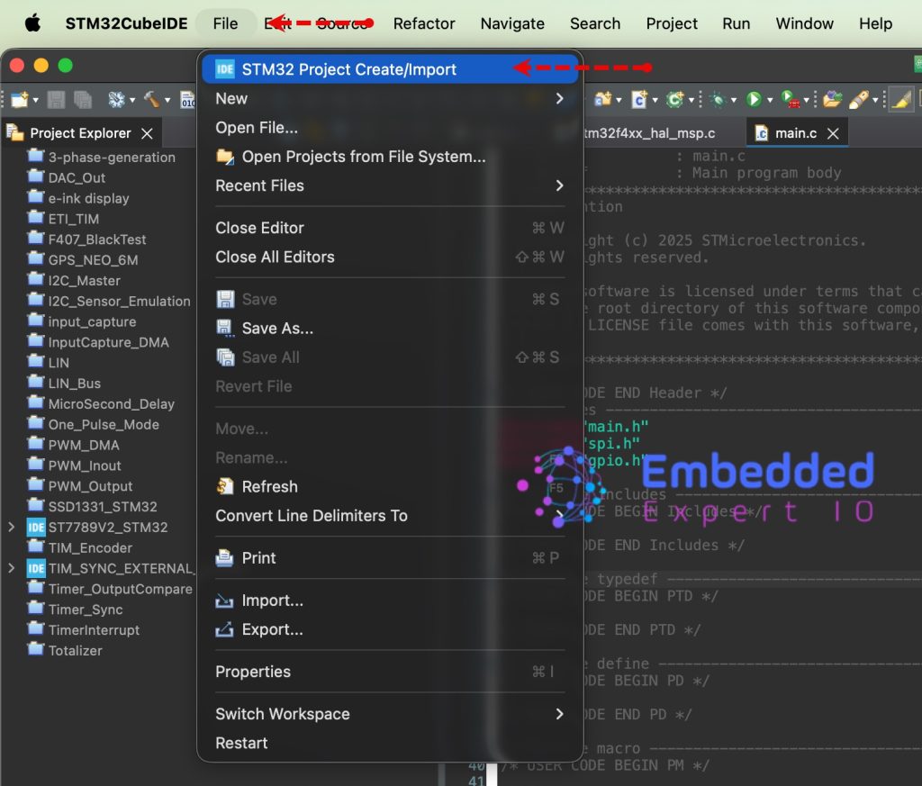
Next, from Import STM32 Project, select STM32CubeMX/STM32CubeIDE Project and click on Next as follows:
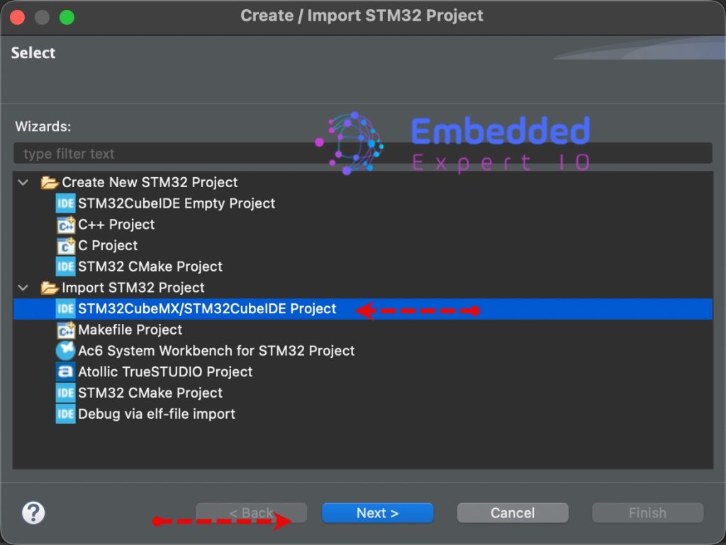
Next, select the folder that contains the .ioc file and click on Finish as follows:
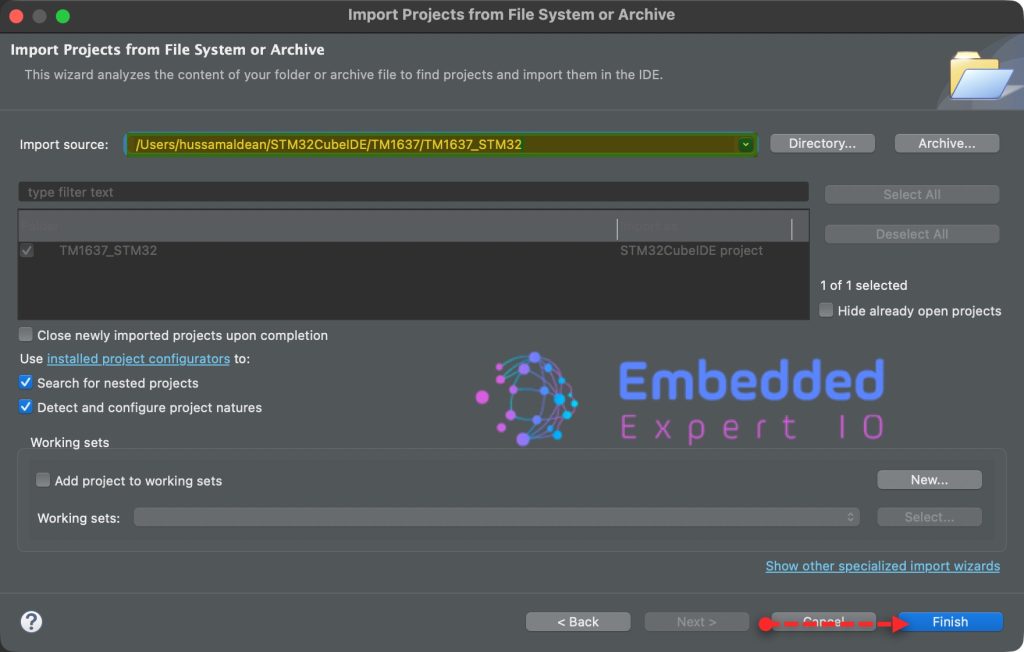
Note: Project name is for reference only.
5. Firmware Development:
We start of by opening main.h and include the stdio.h header file in user include header file as follows:
#include "stdio.h"
Next, open main.c file and in user code begin 0, declare the following function:
int __io_putchar(int ch)
{
	while (!LL_USART_IsActiveFlag_TXE(USART2))
	{

	}

	LL_USART_TransmitData8(USART2, (char)ch);

	return ch;
}
This function shall allow us to use printf over UART.
Next, open i2c.h header file and declare the following function in USER CODE BEGIN Prototypes
uint8_t I2C_Scan(I2C_TypeDef *I2Cx);
The function shall take i2c instant as argument and returns number of the devices connected to the I2C bus.
Next, open i2.c source and in user code begin 1, add the following function:
/**
 * @brief Scans I2C bus for connected slave devices
 * @param I2Cx I2C instance (e.g., I2C1, I2C2, I2C3)
 * @return Number of devices found
 */
uint8_t I2C_Scan(I2C_TypeDef *I2Cx)
{

	    printf("Scanning I2C bus...\r\n\r\n");

	    uint8_t devices_found = 0;

	    // Scan from address 0x08 to 0x77 (valid 7-bit I2C address range)
	    for(uint8_t address = 0x08; address < 0x78; address++)
	    {
	        // Generate START condition
	        LL_I2C_GenerateStartCondition(I2Cx);

	        // Wait for START condition to be generated
	        while(!LL_I2C_IsActiveFlag_SB(I2Cx));

	        // Send address with WRITE bit (LSB = 0)
	        LL_I2C_TransmitData8(I2Cx, (address << 1) | 0x00);

	        // Wait for address to be sent
	        while(!LL_I2C_IsActiveFlag_ADDR(I2Cx) && !LL_I2C_IsActiveFlag_AF(I2Cx));

	        // Check if ACK received (device found)
	        if(LL_I2C_IsActiveFlag_ADDR(I2Cx))
	        {
	            // Device responded
	            printf("Device found at address: 0x%02X\r\n", address);
	            devices_found++;
	        }

	        // Clear ADDR flag
	        LL_I2C_ClearFlag_ADDR(I2Cx);

	        // Clear AF flag if no device
	        LL_I2C_ClearFlag_AF(I2Cx);

	        // Generate STOP condition
	        LL_I2C_GenerateStopCondition(I2Cx);

	        // Small delay between scans
	        LL_mDelay(2);
	    }

	    printf("*****Scan Complete*****\r\n");
	    printf("Total devices found: %d\r\n\r\n", devices_found);
	    return devices_found;

}
1. Loop Initialization
for(uint8_t address = 0x08; address < 0x78; address++)
The function loops through the valid 7-bit I2C address space. In the I2C specification, addresses 0x00 to 0x07 and 0x78 to 0x7F are reserved for special purposes (like General Call or High-Speed mode). Scanning from 0x08 to 0x77 ensures you only target standard slave peripherals.
2. Generating the START Condition
LL_I2C_GenerateStartCondition(I2Cx);
while(!LL_I2C_IsActiveFlag_SB(I2Cx));
This tells the I2C peripheral hardware to pull the SDA line low while SCL remains high, creating a START condition on the bus. The code then enters a blocking while loop, polling the SB (Start Bit) flag inside the Status Register. Execution stays here until the hardware confirms the start sequence has been successfully driven onto the lines.
3. Sending the Target Address
LL_I2C_TransmitData8(I2Cx, (address << 1) | 0x00);
I2C devices require an 8-bit frame consisting of the 7-bit address shifted left by 1 bit, with the Least Significant Bit (LSB) indicating the transaction direction: Read (1) or Write (0). A standard scanner sends a Write bit (0x00) to probe the device.
4. Waiting for a Hardware Verdict
while(!LL_I2C_IsActiveFlag_ADDR(I2Cx) && !LL_I2C_IsActiveFlag_AF(I2Cx));
The execution pauses here to await one of two hardware responses:
ADDR(Address Sent): A peripheral matched the transmitted address and pulled the SDA line low to acknowledge (ACK).AF(Acknowledge Failure): No device responded to the address, leaving the SDA line high (NACK).
5. Evaluating the Result
if(LL_I2C_IsActiveFlag_ADDR(I2Cx))
{
    printf("Device found at address: 0x%02X\r\n", address);
    devices_found++;
}
If the ADDR flag is set, it means a device exists at the current address. The code prints the address to the console and increments your counter.
6. Register and Bus Cleanup
LL_I2C_ClearFlag_ADDR(I2Cx);
LL_I2C_ClearFlag_AF(I2Cx);
LL_I2C_GenerateStopCondition(I2Cx);
After checking the status, the code sequentially clears both the ADDR flag and the AF flag to prepare the registers for the next iteration. Finally, it commands the hardware to generate a STOP condition, releasing the SDA and SCL lines back to an idle state.
7. Bus Stabilization Delay
LL_mDelay(2);
A short 2-millisecond blocking delay allows the physical pull-up resistors on your PCB to bring the SDA and SCL lines safely back up to VCC before the next loop iteration begins.
Next, in main.c file, declare the following global file:
uint8_t NumOfDevices;
In while 1 loop in user code begin 3:
NumOfDevices=I2C_Scan(I2C1);

for (volatile int32_t i=0;i<1000000;i++)
{
  //DO Nothing
}
Thats all for the firmware.
Save, build the project and run it as follows:

You may download the project file from here.
6. Results:
Open your favourite terminal application, set the baudrate to 115200 and you should get something like this:
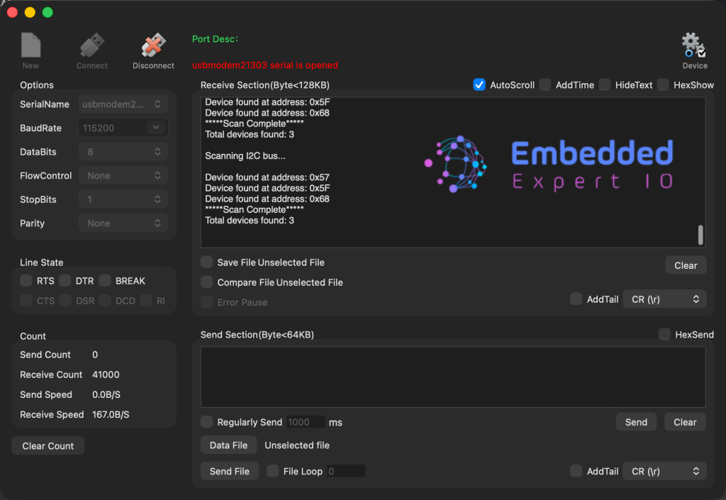
Here is a look for i2c bus:
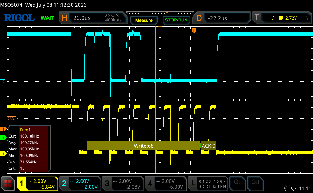
Next, we shall read from register and print the register value.
Stay tuned.
Happy coding 😉

Add Comment