Establish robust, asynchronous serial communication by leveraging the STM32F4’s USART/UART peripheral configured with Low Layer (LL) drivers for maximum data throughput and minimal execution overhead. This guide covers register-level configuration of baud rate generation, frame formats, and status flags, enabling your firmware to efficiently transmit and receive bytes to and from a host computer or external sensors.
In this guide, we shall cover the following:
- Introduction.
- STM32CubeMX setup.
- Importing the project to STM32CubeIDE.
1. Introduction:
While managing internal timing and handling local pins allows an embedded system to control its immediate environment, a truly useful device must communicate with the broader world. The Universal Asynchronous Receiver-Transmitter (UART) is one of the oldest, most robust, and most ubiquitous communication protocols in computing. From debugging system states on a development PC to streaming data from cellular modules, GPS receivers, or industrial sensors, UART serves as the foundational data highway for embedded firmware.
Unlike synchronous protocols (such as SPI or I2C) that share a dedicated clock line between devices to synchronize data bits, UART is completely asynchronous. It relies on both the transmitter (TX) and receiver (RX) agreeing beforehand on a precise transmission speed—known as the Baud Rate—and a specific data packet architecture. This reliance on timing synchronization means that the physical hardware must handle bit-level sampling with extreme precision.
Anatomy of an Asynchronous Data Frame
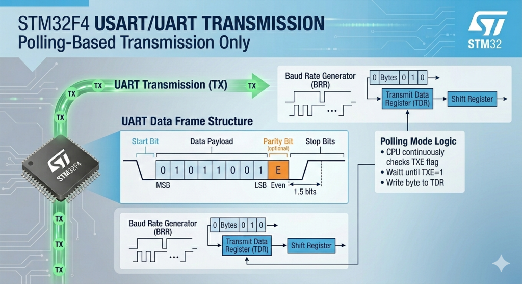
Because there is no shared clock line, a UART line rests in an idle Logic HIGH state. When a transmission begins, the hardware sequences the data into a tightly controlled frame:
- Start Bit: The transmitter pulls the line LOW for exactly one bit period. This sudden high-to-low transition alerts the receiver’s hardware to wake up and start its internal sample counter.
- Data Payload: Typically 8 or 9 bits of data are clocked out sequentially, usually starting with the Least Significant Bit (LSB).
- Parity Bit (Optional): A primitive form of error checking that counts the number of 1s in the payload to verify data integrity over noisy lines.
- Stop Bits: The transmitter pulls the line back to a Logic HIGH state for 1, 1.5, or 2 bit periods to signify the end of the frame and reset the line for the next character.
Low Layer (LL) Control: Maximizing Hardware Efficiency
Configuring UART on the STM32F4 using Low Layer (LL) drivers gives you direct, uncompromising access to the peripheral’s internal registers. Instead of dealing with the multi-layered memory structures and abstract handle states of the HAL library, LL functions expose the immediate status flags of the hardware.
To achieve efficient data transmission and reception, your code will interact directly with the hardware’s core bit-management structures:
- The Transmit Data Register (TDR) and Receive Data Register (RDR): The data buffers where bytes are staged before being shifted out onto the physical copper wire bit-by-bit, or where incoming bits are compiled back into a usable byte.
- The Baud Rate Generator (BRR): A highly precise register that divides the peripheral’s internal clock source ($f_{PCLK}$) down to the exact frequency required for the chosen baud rate (e.g., 115200 bps).
- Status Flags (TXE and RXNE): Real-time hardware status indicators.
TXE(Transmit Data Register Empty) tells your code the hardware is ready to accept a new byte, whileRXNE(Read Data Register Not Empty) signals that a fresh byte has successfully arrived over the wire and is waiting to be processed.
By managing these registers directly, you eliminate execution overhead, allowing you to build lean communication drivers. This forms the perfect foundation for everything from high-speed data logging to parsing dense AT-command streams from external wireless hardware.
2. STM32CubeMX Setup:
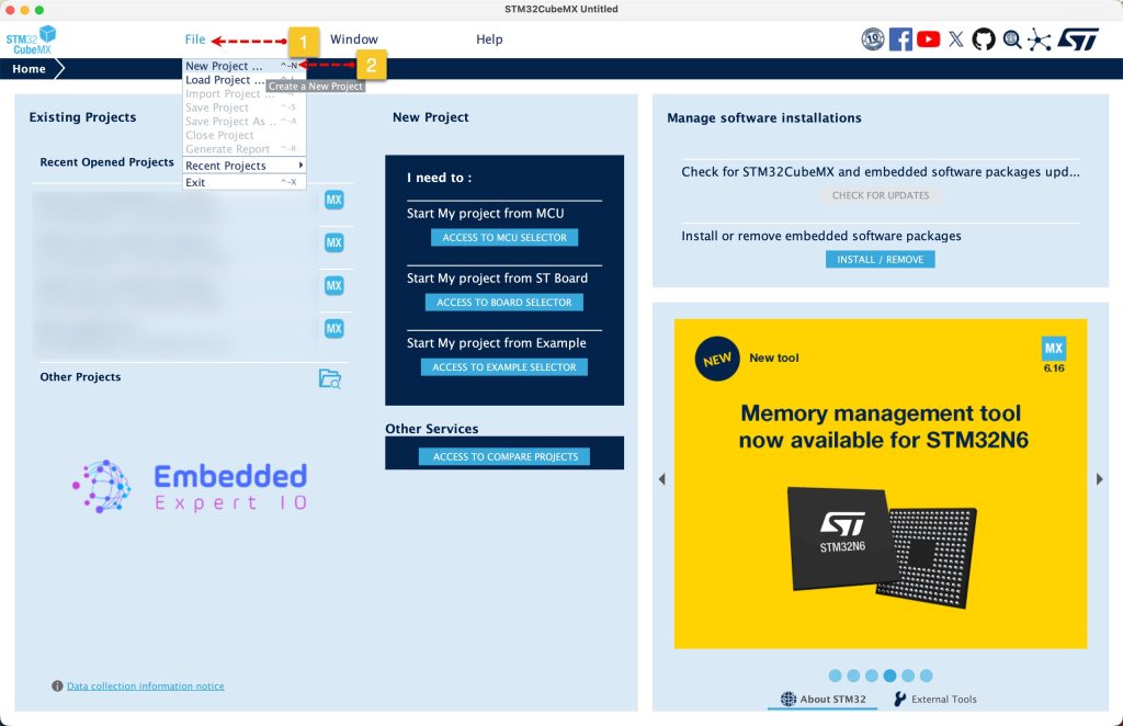
Open STM32CubeMX as start a new project as follows:
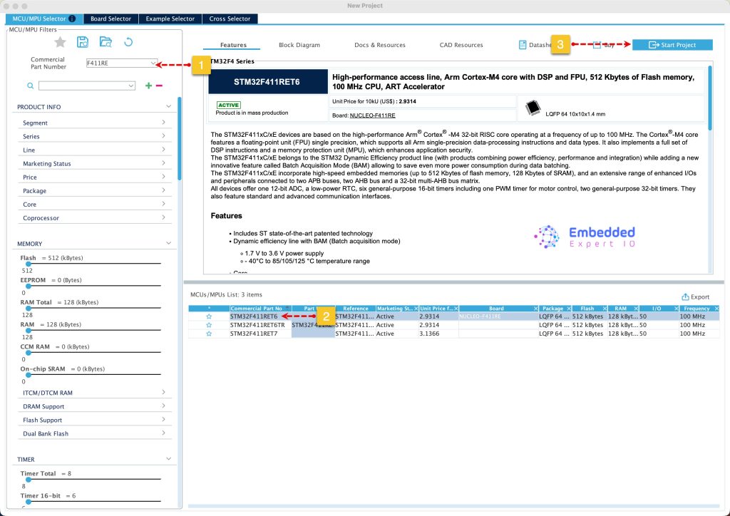
Search for your STM32 MCU, select the MCU and click on Start New Project as follows:
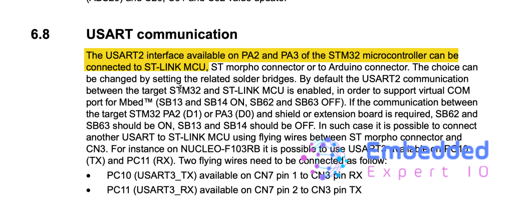
From the user manual of STM32F411 Nucleo-64, we can find that PA2 and PA3 are connected to ST-Link MCU which corresponds to USART2 as follows:
From Connectivity, enable UASRT2 as Asynchronous mode as follows:
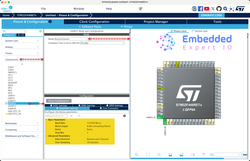
Keep the configuration as is since we shall use the UART to transmit the data in polling mode.
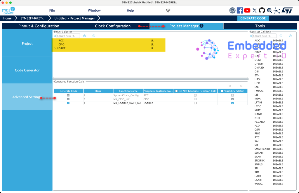
Next, from Project Manager, Advanced Settings tab, set RCC, GPIO and USART to LL as follows:
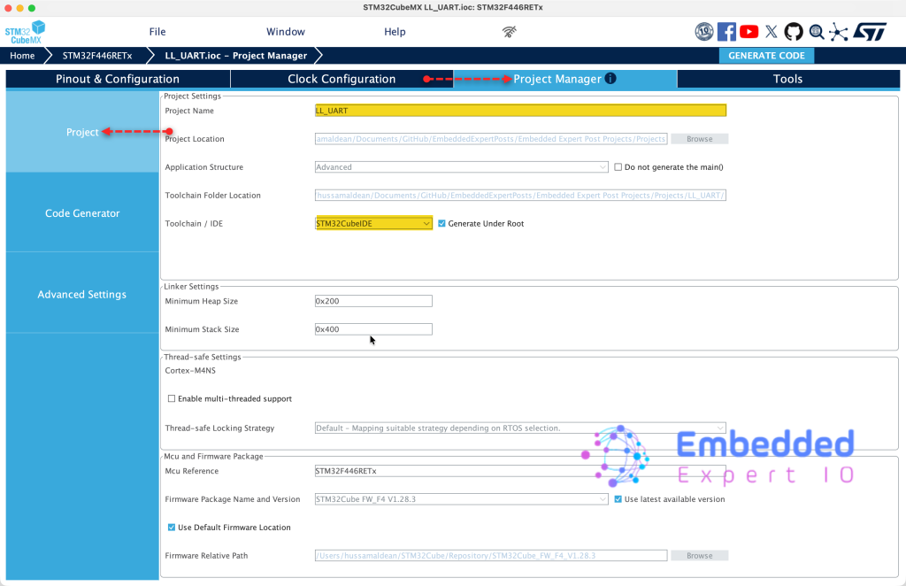
Finally, from Project Manager, Project tab, give the project a name and set toolchain/IDE to STM32CubeIDE as follows:
That all for the configuration.
3. Importing the Project to STM32CubeIDE:
Open STM32CubeIDE, select your workspace and click on Launch.
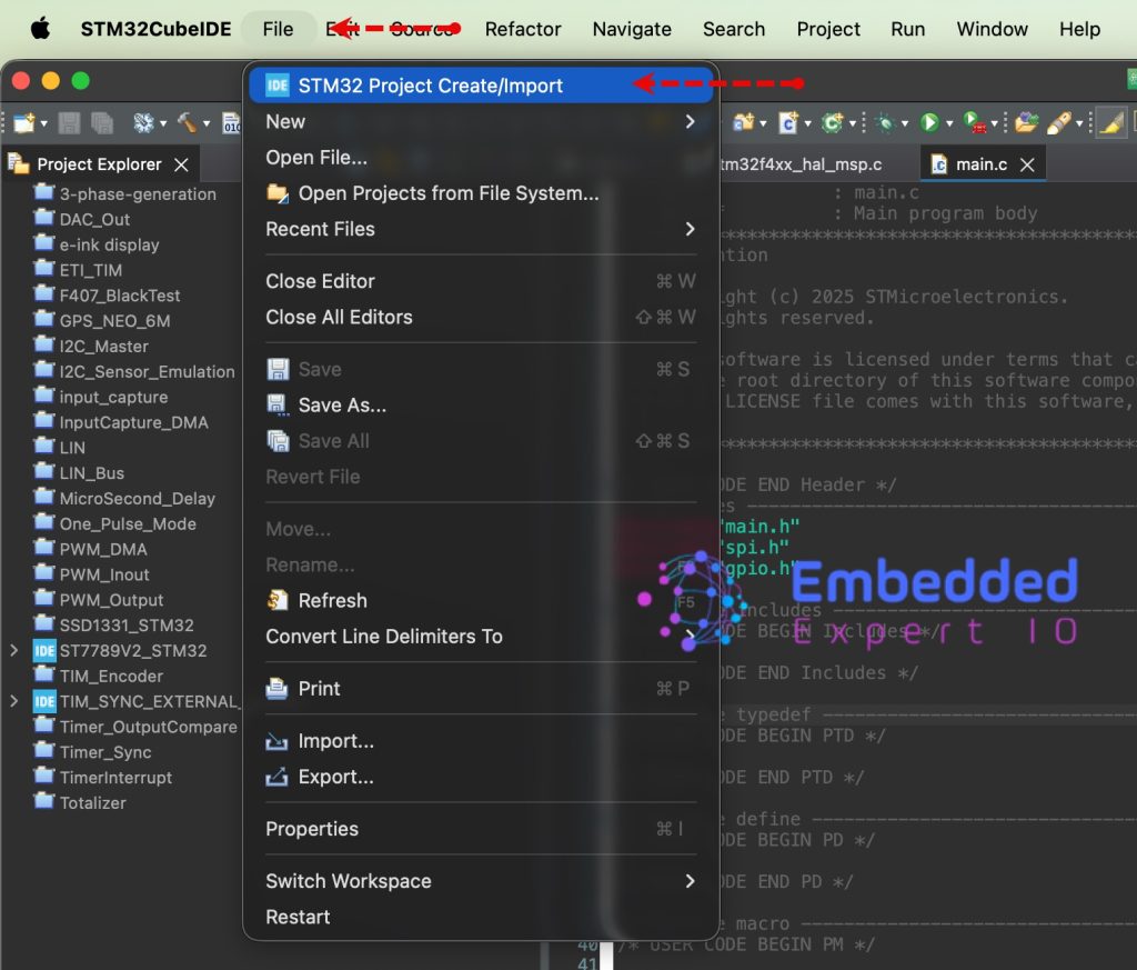
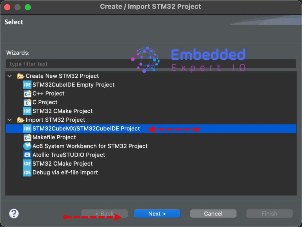
From the IDE, click File and select STM32 Project Create/Import as follows:
Next, from Import STM32 Project, select STM32CubeMX/STM32CubeIDE Project and click on Next as follows:
Next, select the folder that contains the .ioc file and click on Finish as follows:
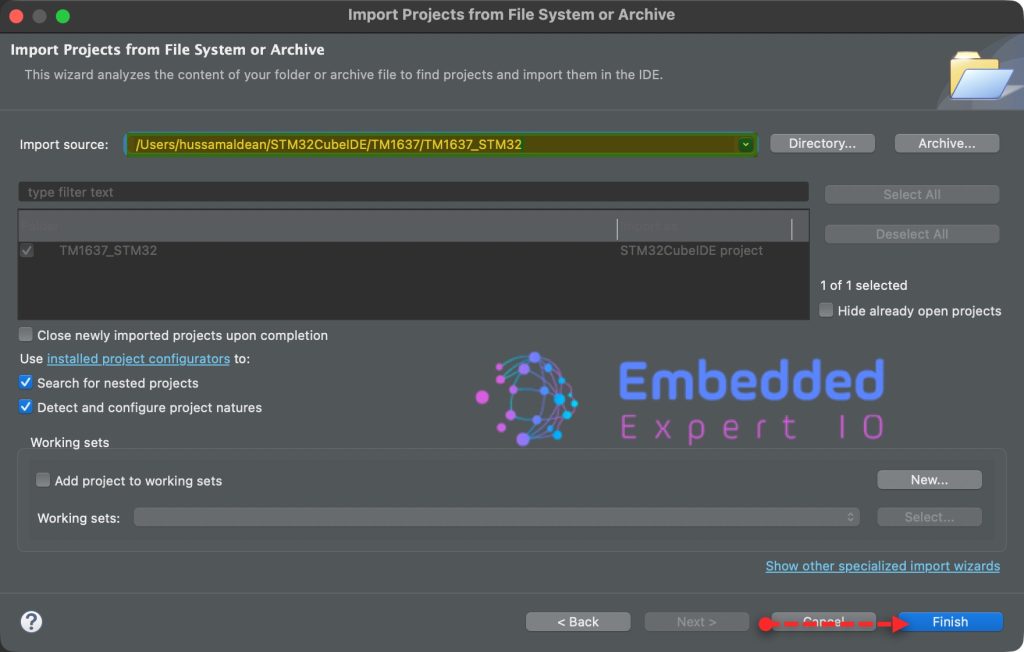
Note: Project name is for reference only.
4. Firmware Development:
In this guide, we shall cover two methods to send the data, using single character and the user has to handle how to send the data and how to send the string directly by providing the buffer and length of the buffer.
We shall start with single character.
We start by including stdio.h header file as follows:
#include "stdio.h"
Next, in user code begin PV, declare the following three variables:
char uart_buff[50]={0};
uint8_t counter;
uint16_t buff_len;- uart_buff[50] which holds the characters to be sent over uart.
- counter to counts number of times the uart send the data.
- buff_len which holds the buffer length to be sent.
Next, in user code begin 0, declare a function that shall send single character as follows:
void UART_Send_Char(char ch)
{
	while (!LL_USART_IsActiveFlag_TXE(USART2));   	// Wait until TX buffer is empty

	LL_USART_TransmitData8(USART2, ch);				// Send byte

	while (!LL_USART_IsActiveFlag_TC(USART2));		// Wait for complete transmission
}
This function handles transmitting a single character over UART using blocking polling mode. It relies on a two-step hardware buffer process to ensure the data is safely sent out of the physical pin without corruption.
Step-by-Step Breakdown
1. Wait for the Transmit Data Register (TXE)
while (!LL_USART_IsActiveFlag_TXE(USART2));
The CPU blocks and continuously polls the TXE (Transmit Data Register Empty) flag. It waits here until the internal TDR buffer is empty and ready to accept a new byte. If a previous character is still sitting in the buffer, this line prevents it from being overwritten.
2. Load Data into the Buffer
LL_USART_TransmitData8(USART2, ch);
Once TXE is true, the CPU writes the 8-bit character ch directly into the USART2->DR register. The hardware immediately moves this byte from the TDR buffer into an internal hardware Shift Register, which begins clocking the data out onto the TX pin bit-by-bit (Start bit, data bits, stop bit).
3. Wait for Complete Transmission (TC)
while (!LL_USART_IsActiveFlag_TC(USART2));
The CPU blocks a second time, polling the TC (Transmission Complete) flag. This flag only turns true when the shift register has finished physically clocking every single bit of the frame out of the microcontroller.
Next, in while 1 loop in user code begin 3:
buff_len=sprintf(uart_buff,"Counter Value =%d \r\n",counter++);
for (int i=0;i<buff_len;i++)
{
  UART_Send_Char(uart_buff[i]);
}
This code snippet formats a dynamic string containing an incrementing counter value and transmits it character-by-character over the UART interface.
Step-by-Step Breakdown
1. String Formatting via sprintf
The system constructs a formatted text string inside a character array named uart_buff. The current value of the countervariable replaces the %d placeholder, and the variable is then incremented by one so it is ready for the next cycle. The sprintf function returns the exact number of characters written to the buffer (excluding the null terminator), which is saved into buff_len to serve as the precise loop boundary.
2. Character-by-Character Transmission
A sequential loop iterates through the populated uart_buff array, starting at index zero and ending just before reaching buff_len. During each iteration, the loop extracts a single character from the array—such as ‘C’, then ‘o’, then ‘u’—and feeds it directly into your blocking transmission function to be physically clocked out over the microcontroller’s TX pin.
Finally, Save, build the project and run it as follows:

Open your favourite terminal application, set the baudrate to 115200 and you should get the following:
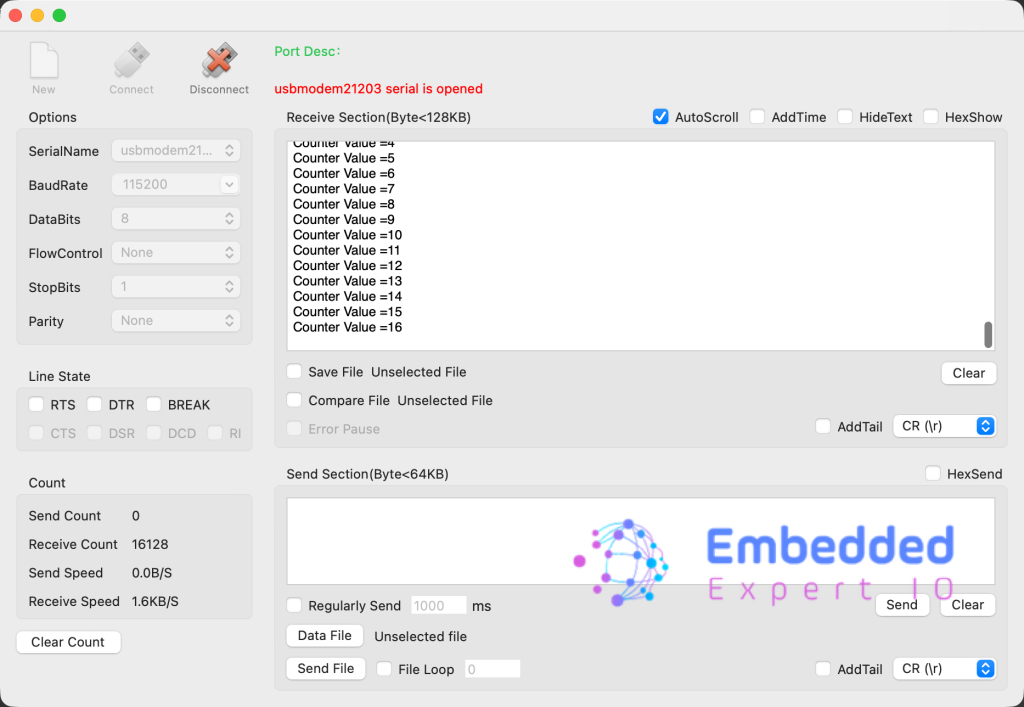
Next, we shall see how to send string using single function.
In user code begin 0, declare the following function:
void UART_Send_String(char *ch , uint16_t len)

{
	for (int i=0;i<len;i++)
	{
		while (!LL_USART_IsActiveFlag_TXE(USART2));   	// Wait until TX buffer is empty

		LL_USART_TransmitData8(USART2, ch[i]);				// Send byte

	}

	while (!LL_USART_IsActiveFlag_TC(USART2));		// Wait for complete transmission
}
This will allow you send multiple bytes as fast as possible.
In user code begin 3 in while function:
buff_len=sprintf(uart_buff,"Counter Value =%d \r\n",counter++);
UART_Send_String(uart_buff,buff_len);
LL_mDelay(10);
Finally, Save, build the project and run it as follows:
Open your favourite terminal application, set the baudrate to 115200 and you should get the following:
Congratulations, you send the string successfully.
You may download the project from here.
Happy coding 😉
Add Comment