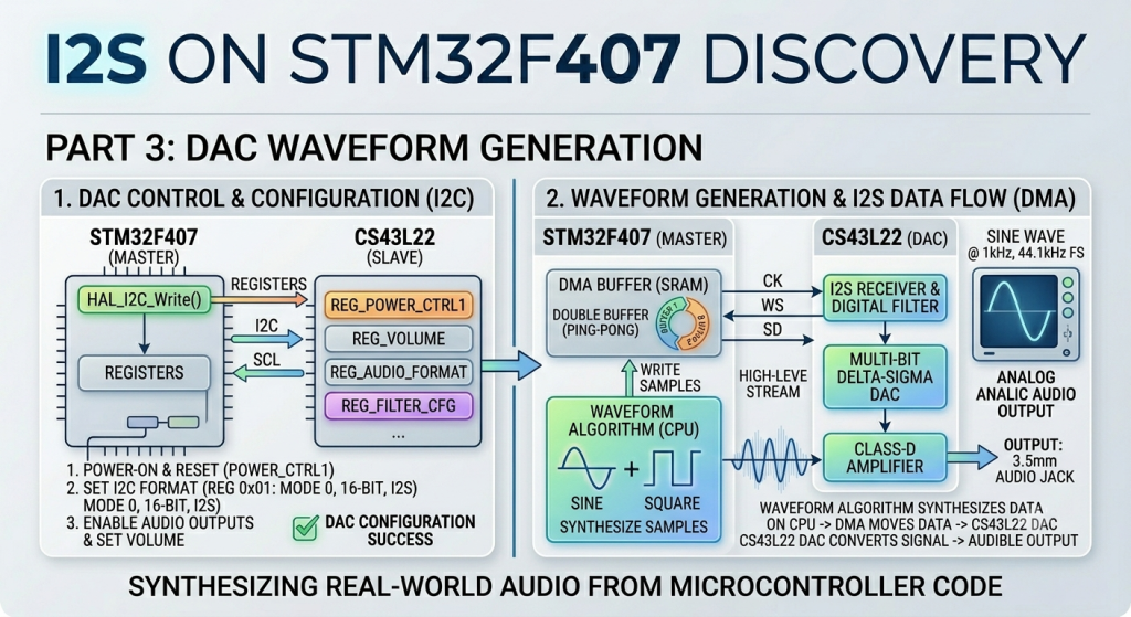
Now that the basic DMA transmission pipeline is established, the final part of this guide focuses on interfacing the STM32F407 with the onboard CS43L22 audio DAC to produce real-world audio waveforms. By configuring the DAC via $I^2C$ for control signaling and feeding it continuous audio samples via I2S, you will synthesize stable, audible signals like sine or sawtooth waves directly through the board’s 3.5mm audio jack.
In this guide, we shall cover the following:
- Introduction.
- STM32CubeMX setup.
- Firmware Development.
- Results.
1. Introduction:
Introducing the CS43L22 Audio DAC
The CS43L22 is a highly integrated, low-power stereo audio DAC and headphone/speaker amplifier designed by Cirrus Logic. On the STM32F407 Discovery board, this chip acts as the bridge between your raw digital software algorithms and the analog world, turning numbers into real-world sound waves accessible through the onboard 3.5mm blue audio jack.
Equipped with a digital signal processing engine, an onboard multi-bit Delta-Sigma modulator, and a Class-D speaker driver alongside a stereo headphone amplifier, it manages complex digital-to-analog conversions efficiently while minimizing external component requirements.
Real-World Applications
Integrating an external I2S DAC with an STM32 processing core unlocks a wide variety of embedded audio applications:
- Waveform & Function Generators: Synthesizing precise, adjustable analog signals (such as sine, square, sawtooth, or triangle waves) for laboratory testing, calibration tools, or musical synthesizers.
- Embedded Audio Players: Reading compressed or uncompressed audio files (like
.wavor.mp3) from an SD card or external flash memory and streaming them directly to a headset or speaker interface. - Voice Alerts & Industrial Telemetry: Adding high-quality spoken voice prompts, alarms, and status indicators to industrial equipment, smart home appliances, or medical devices.
- Real-Time Digital Signal Processing (DSP): Implementing real-time digital filtering, equalization, audio effects (such as reverb, delay, or pitch shifting), or mixing multiple independent audio channels into a single output stream.
2. STM32CubeMX Setup:
Open the project .ioc file with STM32CubeMX.
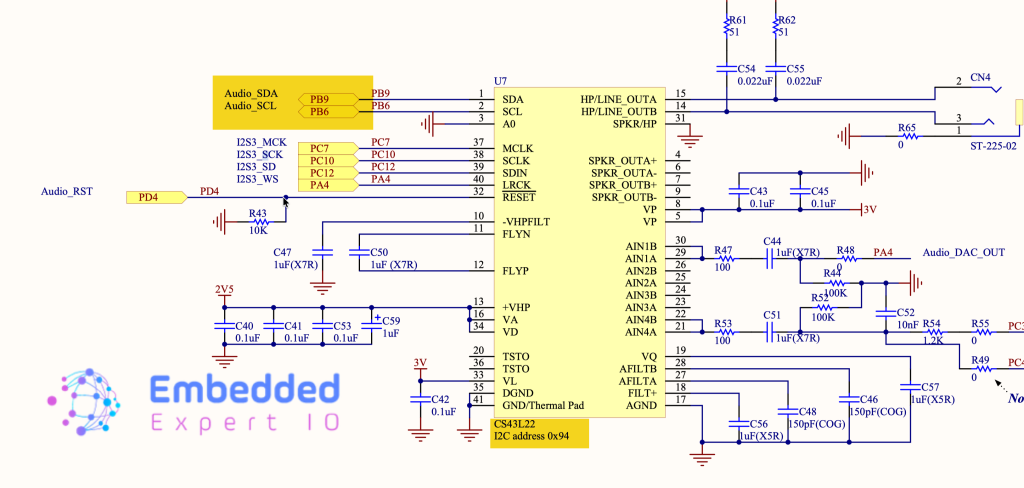
Next, we need to find which pins are connected to the I2C of the DAC. From the schematic of the board, we can find the following:
- PB9 for SDA
- PB6 for SCL
Also, take a note of the address mentioned which is needed later.
Next, from STM32CubeMX, set PB6 and PB9 to I2C1 and enable I2C1 as follows:
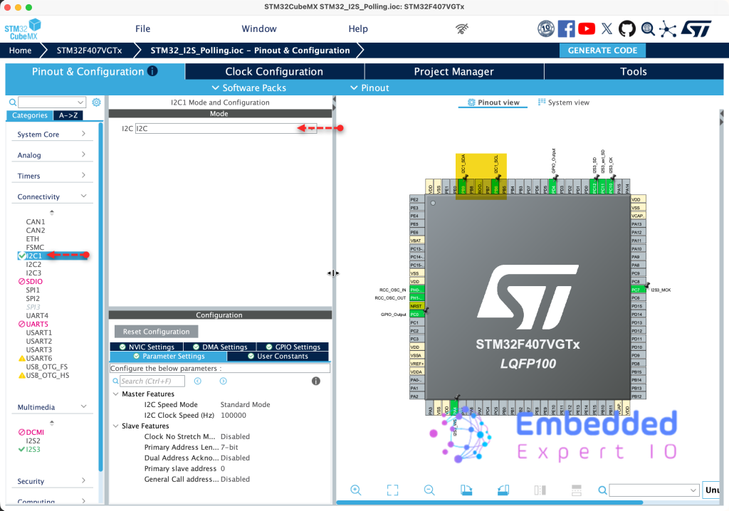
Keep the parameters at the default values since we are only initialize the DAC once.
Next, from I2S section, reduce the Audio frequency from 192 to 96KHz and generate the code as follows:
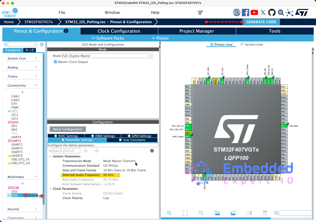
Thats all for the STM32CubeMX configuration.
3. Firmware Development:
Open the project in STM32CubeIDE.
We start by creating new header and source file with name of CS43L22.h and CS43L22.c respectively.
To create the source file:
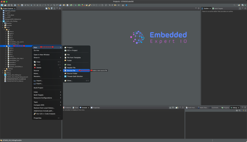
Next, give it a name and click on Finish.

To create the header file:
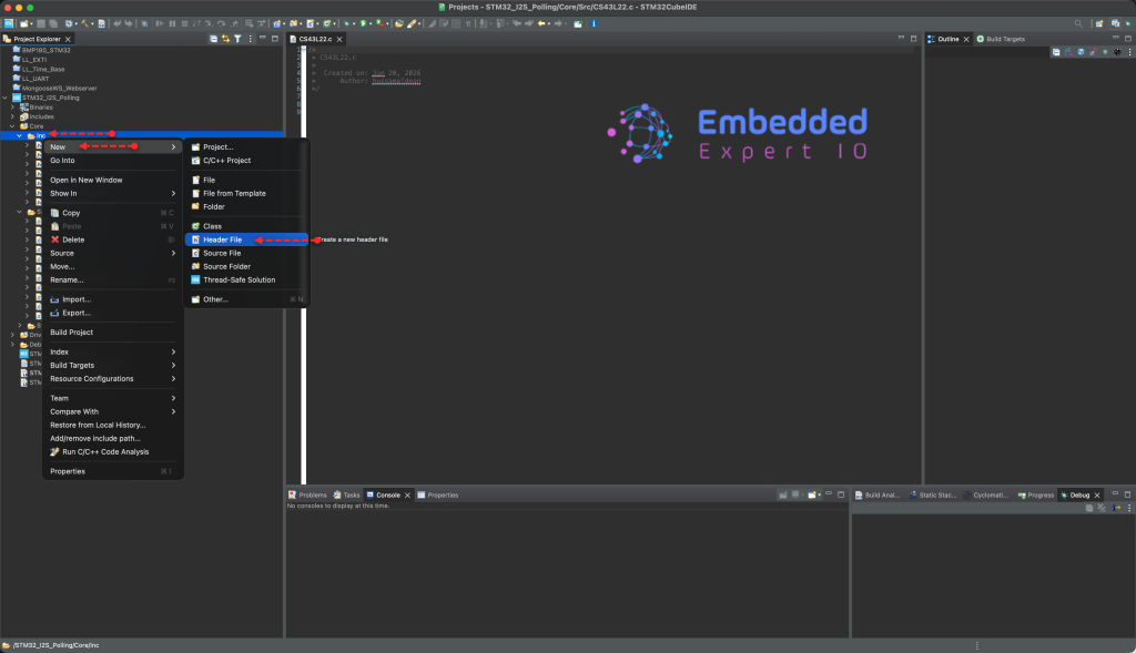
Next, give it a name and click on Finish.
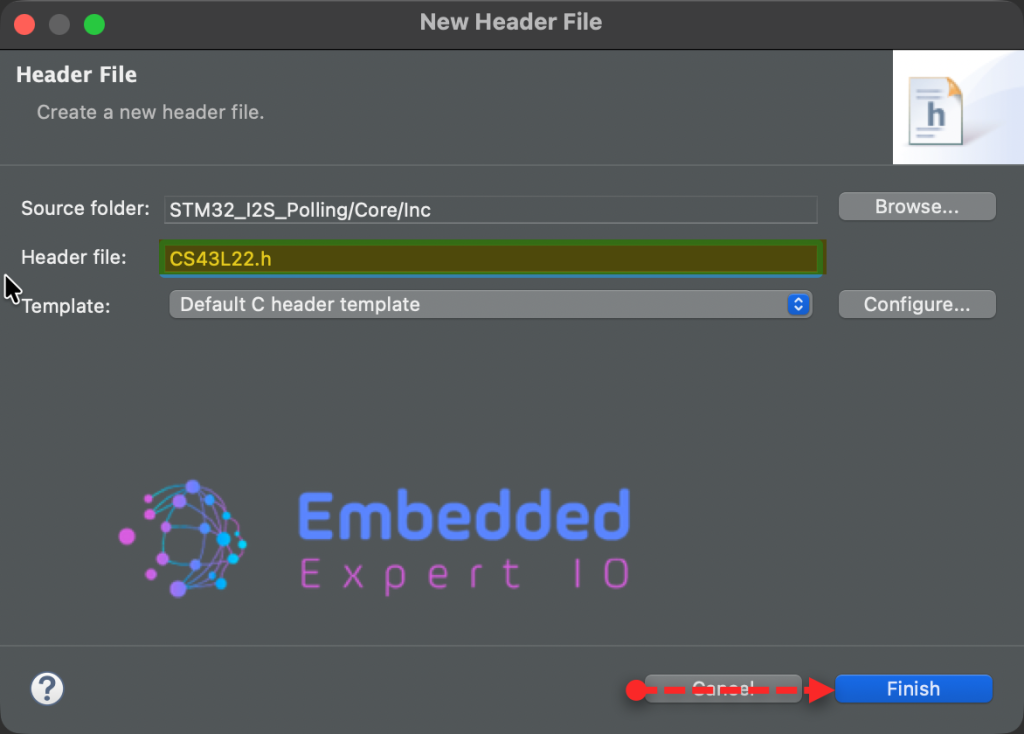
Once the header and source files have been created, open the header.
We start by including the following header files:
#include "stdint.h"
Next, declare the address of the DAC:
#define DAC_I2C_ADDR (0x94)
Next, define all the required registers addresses a
#define POWER_CONTROL1				0x02
#define POWER_CONTROL2				0x04
#define CLOCKING_CONTROL 	  		0x05
#define INTERFACE_CONTROL1			0x06
#define INTERFACE_CONTROL2			0x07
#define PASSTHROUGH_A				0x08
#define PASSTHROUGH_B				0x09
#define MISCELLANEOUS_CONTRLS		0x0E
#define PLAYBACK_CONTROL			0x0F
#define PASSTHROUGH_VOLUME_A		0x14
#define PASSTHROUGH_VOLUME_B		0x15
#define PCM_VOLUME_A				0x1A
#define PCM_VOLUME_B				0x1B
#define CONFIG_00					0x00
#define CONFIG_47					0x47
#define CONFIG_32					0x32

#define CS43L22_REG_MASTER_A_VOL    0x20
#define CS43L22_REG_MASTER_B_VOL    0x21

#define CS43_MUTE				 	0x00

#define CS43_RIGHT					0x01
#define CS43_LEFT				 	0x02
#define CS43_RIGHT_LEFT	 			0x03

#define VOLUME_CONVERT_A(Volume)    (((Volume) > 100)? 255:((uint8_t)(((Volume) * 255) / 100)))
#define VOLUME_CONVERT_D(Volume)    (((Volume) > 100)? 24:((uint8_t)((((Volume) * 48) / 100) - 24)))
Next, declare an enumeration to hold the operation mode:
typedef enum
{
	CS43L22_MODE_I2S = 0,
	CS43L22_M
}CS43_MODE;
Declare the following functions:
void CS43_Init(CS43_MODE outputMode);
void CS43_Enable_RightLeft(uint8_t side);
void CS43_SetVolume(uint8_t volume);
void CS43_Start(void);
void CS43_Stop(void);
void CS43L22_RST_Pin_Low(void);
void CS43L22_RST_Pin_High(void);
Hence, the header file as follows:
#ifndef INC_CS43L22_H_
#define INC_CS43L22_H_


#include "stdint.h"


#define DAC_I2C_ADDR 				(0x94)

#define POWER_CONTROL1				0x02
#define POWER_CONTROL2				0x04
#define CLOCKING_CONTROL 	  		0x05
#define INTERFACE_CONTROL1			0x06
#define INTERFACE_CONTROL2			0x07
#define PASSTHROUGH_A				0x08
#define PASSTHROUGH_B				0x09
#define MISCELLANEOUS_CONTRLS		0x0E
#define PLAYBACK_CONTROL			0x0F
#define PASSTHROUGH_VOLUME_A		0x14
#define PASSTHROUGH_VOLUME_B		0x15
#define PCM_VOLUME_A				0x1A
#define PCM_VOLUME_B				0x1B
#define CONFIG_00					0x00
#define CONFIG_47					0x47
#define CONFIG_32					0x32

#define CS43L22_REG_MASTER_A_VOL    0x20
#define CS43L22_REG_MASTER_B_VOL    0x21

#define CS43_MUTE				 	0x00

#define CS43_RIGHT					0x01
#define CS43_LEFT				 	0x02
#define CS43_RIGHT_LEFT	 			0x03

#define VOLUME_CONVERT_A(Volume)    (((Volume) > 100)? 255:((uint8_t)(((Volume) * 255) / 100)))
#define VOLUME_CONVERT_D(Volume)    (((Volume) > 100)? 24:((uint8_t)((((Volume) * 48) / 100) - 24)))

typedef enum
{
	CS43L22_MODE_I2S = 0,
	CS43L22_MODE_ANALOG,
}CS43_MODE;

void CS43_Init(CS43_MODE outputMode);
void CS43_Enable_RightLeft(uint8_t side);
void CS43_SetVolume(uint8_t volume);
void CS43_Start(void);
void CS43_Stop(void);
void CS43L22_RST_Pin_Low(void);
void CS43L22_RST_Pin_High(void);


#endif /* INC_CS43L22_H_ */
Next, open CS43L22.c source file:
Include the following header diles:
#include "CS43L22.h"

#include "i2c.h"
Next, declare an array to hold the configuration data to be sent as follows:
static uint8_t iData[2];
Next, declare functions that will allow us to write/read to/from a register as follows:
// Function(1): Write to register
static void write_register(uint8_t reg, uint8_t *data)
{
	iData[0] = reg;


	HAL_I2C_Mem_Write(&hi2c1, DAC_I2C_ADDR, reg, 1, data, 1, 10);


}
// Function(2): Read from register
static void read_register(uint8_t reg, uint8_t *data)
{
	uint8_t tempData=0;

	HAL_I2C_Mem_Read(&hi2c1, DAC_I2C_ADDR, reg, 1, &tempData, 1, 10);

	*data=tempData;
}
Next, helper function to set the RST pin state:
void CS43L22_RST_Pin_Low(void)
{
	HAL_GPIO_WritePin(GPIOD, GPIO_PIN_4, RESET);
}

void CS43L22_RST_Pin_High(void)
{
	HAL_GPIO_WritePin(GPIOD, GPIO_PIN_4, SET);
}
Next, the initialization sequence:
void CS43_Init(CS43_MODE outputMode)
{


	CS43L22_RST_Pin_High();

	//(2): Power down
	iData[1] = 0x01;
	write_register(POWER_CONTROL1,iData);

	//(3): Enable Right and Left headphones
	iData[1] =  (2 << 6);  // PDN_HPB[0:1]  = 10 (HP-B always onCon)
	iData[1] |= (2 << 4);  // PDN_HPA[0:1]  = 10 (HP-A always on)
	iData[1] |= (3 << 2);  // PDN_SPKB[0:1] = 11 (Speaker B always off)
	iData[1] |= (3 << 0);  // PDN_SPKA[0:1] = 11 (Speaker A always off)
	write_register(POWER_CONTROL2,&iData[1]);

	//(4): Automatic clock detection
	iData[1] = (1 << 7);
	write_register(CLOCKING_CONTROL,&iData[1]);

	//(5): Interface control 1
	read_register(INTERFACE_CONTROL1, iData);
	iData[1] &= (1 << 5); // Clear all bits except bit 5 which is reserved
	iData[1] &= ~(1 << 7);  // Slave
	iData[1] &= ~(1 << 6);  // Clock polarity: Not inverted
	iData[1] &= ~(1 << 4);  // No DSP mode
	iData[1] &= ~(1 << 2);  // Left justified, up to 24 bit (default)
	iData[1] |= (1 << 2);
	iData[1] |=  (3 << 0);  // 16-bit audio word length for I2S interface
	write_register(INTERFACE_CONTROL1,&iData[1]);


	//(6): Passthrough A settings
	read_register(PASSTHROUGH_A, &iData[1]);
	iData[1] &= 0xF0;      // Bits [4-7] are reserved
	iData[1] |=  (1 << 0); // Use AIN1A as source for passthrough
	write_register(PASSTHROUGH_A,&iData[1]);


	//(7): Passthrough B settings
	read_register(PASSTHROUGH_B, &iData[1]);
	iData[1] &= 0xF0;      // Bits [4-7] are reserved
	iData[1] |=  (1 << 0); // Use AIN1B as source for passthrough
	write_register(PASSTHROUGH_B,&iData[1]);


	//(8): Miscellaneous register settings
	read_register(MISCELLANEOUS_CONTRLS, &iData[1]);
	if(outputMode == CS43L22_MODE_ANALOG)
	{
		iData[1] |=  (1 << 7);   // Enable passthrough for AIN-A
		iData[1] |=  (1 << 6);   // Enable passthrough for AIN-B
		iData[1] &= ~(1 << 5);   // Unmute passthrough on AIN-A
		iData[1] &= ~(1 << 4);   // Unmute passthrough on AIN-B
		iData[1] &= ~(1 << 3);   // Changed settings take affect immediately
	}
	else if(outputMode == CS43L22_MODE_I2S)
	{
		iData[1] = 0x02;
	}
	write_register(MISCELLANEOUS_CONTRLS,&iData[1]);
	//(9): Unmute headphone and speaker

	read_register(PLAYBACK_CONTROL, &iData[1]);
	iData[1] = 0x00;
	write_register(PLAYBACK_CONTROL,&iData[1]);

	//(10): Set volume to default (0dB)
	iData[1] = 0x00;
	write_register(PASSTHROUGH_VOLUME_A,&iData[1]);
	write_register(PASSTHROUGH_VOLUME_B,&iData[1]);
	write_register(PCM_VOLUME_A,&iData[1]);
	write_register(PCM_VOLUME_B,&iData[1]);
}
Next, set the channel, either left, right or both:
// Function(2): Enable Right and Left headphones
void CS43_Enable_RightLeft(uint8_t side)
{
	switch (side)
	{
		case 0:
			iData[1] =  (3 << 6);  // PDN_HPB[0:1]  = 10 (HP-B always onCon)
			iData[1] |= (3 << 4);  // PDN_HPA[0:1]  = 10 (HP-A always on)
			break;
		case 1:
			iData[1] =  (2 << 6);  // PDN_HPB[0:1]  = 10 (HP-B always onCon)
			iData[1] |= (3 << 4);  // PDN_HPA[0:1]  = 10 (HP-A always on)
			break;
		case 2:
			iData[1] =  (3 << 6);  // PDN_HPB[0:1]  = 10 (HP-B always onCon)
			iData[1] |= (2 << 4);  // PDN_HPA[0:1]  = 10 (HP-A always on)
			break;
		case 3:
			iData[1] =  (2 << 6);  // PDN_HPB[0:1]  = 10 (HP-B always onCon)
			iData[1] |= (2 << 4);  // PDN_HPA[0:1]  = 10 (HP-A always on)
			break;
		default:
			break;
	}
	iData[1] |= (3 << 2);  // PDN_SPKB[0:1] = 11 (Speaker B always off)
	iData[1] |= (3 << 0);  // PDN_SPKA[0:1] = 11 (Speaker A always off)
	write_register(POWER_CONTROL2,&iData[1]);
}
Set volume:
void CS43_SetVolume(uint8_t volume)
{
	int8_t tempVol = volume - 50;
	tempVol = tempVol*(127/50);
	uint8_t myVolume =  (uint8_t )tempVol;
	iData[1] = myVolume;
	write_register(PASSTHROUGH_VOLUME_A,&iData[1]);
	write_register(PASSTHROUGH_VOLUME_B,&iData[1]);

	iData[1] = VOLUME_CONVERT_D(volume);

	/* Set the Master volume */
	write_register(CS43L22_REG_MASTER_A_VOL,&iData[1]);
	write_register(CS43L22_REG_MASTER_B_VOL,&iData[1]);
}
Start and stop the DAC:
void CS43_Start(void)
{
	// Write 0x99 to register 0x00.
	iData[1] = 0x99;
	write_register(CONFIG_00,&iData[1]);
	// Write 0x80 to register 0x47.
	iData[1] = 0x80;
	write_register(CONFIG_47,&iData[1]);
	// Write '1'b to bit 7 in register 0x32.
	read_register(CONFIG_32, &iData[1]);
	iData[1] |= 0x80;
	write_register(CONFIG_32,&iData[1]);
	// Write '0'b to bit 7 in register 0x32.
	read_register(CONFIG_32, &iData[1]);
	iData[1] &= ~(0x80);
	write_register(CONFIG_32,&iData[1]);
	// Write 0x00 to register 0x00.
	iData[1] = 0x00;
	write_register(CONFIG_00,&iData[1]);
	//Set the "Power Ctl 1" register (0x02) to 0x9E
	iData[1] = 0x9E;
	write_register(POWER_CONTROL1,&iData[1]);
}

void CS43_Stop(void)
{
	iData[1] = 0x01;
	write_register(POWER_CONTROL1,&iData[1]);
}
Hence, the entire source code as follows:
#include "CS43L22.h"

#include "i2c.h"

static uint8_t iData[2];


// Function(1): Write to register
static void write_register(uint8_t reg, uint8_t *data)
{
	iData[0] = reg;


	HAL_I2C_Mem_Write(&hi2c1, DAC_I2C_ADDR, reg, 1, data, 1, 10);


}
// Function(2): Read from register
static void read_register(uint8_t reg, uint8_t *data)
{
	uint8_t tempData=0;

	HAL_I2C_Mem_Read(&hi2c1, DAC_I2C_ADDR, reg, 1, &tempData, 1, 10);

	*data=tempData;
}


void CS43L22_RST_Pin_Low(void)
{
	HAL_GPIO_WritePin(GPIOD, GPIO_PIN_4, RESET);
}

void CS43L22_RST_Pin_High(void)
{
	HAL_GPIO_WritePin(GPIOD, GPIO_PIN_4, SET);
}

void CS43_Init(CS43_MODE outputMode)
{


	CS43L22_RST_Pin_High();

	//(2): Power down
	iData[1] = 0x01;
	write_register(POWER_CONTROL1,iData);

	//(3): Enable Right and Left headphones
	iData[1] =  (2 << 6);  // PDN_HPB[0:1]  = 10 (HP-B always onCon)
	iData[1] |= (2 << 4);  // PDN_HPA[0:1]  = 10 (HP-A always on)
	iData[1] |= (3 << 2);  // PDN_SPKB[0:1] = 11 (Speaker B always off)
	iData[1] |= (3 << 0);  // PDN_SPKA[0:1] = 11 (Speaker A always off)
	write_register(POWER_CONTROL2,&iData[1]);

	//(4): Automatic clock detection
	iData[1] = (1 << 7);
	write_register(CLOCKING_CONTROL,&iData[1]);

	//(5): Interface control 1
	read_register(INTERFACE_CONTROL1, iData);
	iData[1] &= (1 << 5); // Clear all bits except bit 5 which is reserved
	iData[1] &= ~(1 << 7);  // Slave
	iData[1] &= ~(1 << 6);  // Clock polarity: Not inverted
	iData[1] &= ~(1 << 4);  // No DSP mode
	iData[1] &= ~(1 << 2);  // Left justified, up to 24 bit (default)
	iData[1] |= (1 << 2);
	iData[1] |=  (3 << 0);  // 16-bit audio word length for I2S interface
	write_register(INTERFACE_CONTROL1,&iData[1]);


	//(6): Passthrough A settings
	read_register(PASSTHROUGH_A, &iData[1]);
	iData[1] &= 0xF0;      // Bits [4-7] are reserved
	iData[1] |=  (1 << 0); // Use AIN1A as source for passthrough
	write_register(PASSTHROUGH_A,&iData[1]);


	//(7): Passthrough B settings
	read_register(PASSTHROUGH_B, &iData[1]);
	iData[1] &= 0xF0;      // Bits [4-7] are reserved
	iData[1] |=  (1 << 0); // Use AIN1B as source for passthrough
	write_register(PASSTHROUGH_B,&iData[1]);


	//(8): Miscellaneous register settings
	read_register(MISCELLANEOUS_CONTRLS, &iData[1]);
	if(outputMode == CS43L22_MODE_ANALOG)
	{
		iData[1] |=  (1 << 7);   // Enable passthrough for AIN-A
		iData[1] |=  (1 << 6);   // Enable passthrough for AIN-B
		iData[1] &= ~(1 << 5);   // Unmute passthrough on AIN-A
		iData[1] &= ~(1 << 4);   // Unmute passthrough on AIN-B
		iData[1] &= ~(1 << 3);   // Changed settings take affect immediately
	}
	else if(outputMode == CS43L22_MODE_I2S)
	{
		iData[1] = 0x02;
	}
	write_register(MISCELLANEOUS_CONTRLS,&iData[1]);
	//(9): Unmute headphone and speaker

	read_register(PLAYBACK_CONTROL, &iData[1]);
	iData[1] = 0x00;
	write_register(PLAYBACK_CONTROL,&iData[1]);

	//(10): Set volume to default (0dB)
	iData[1] = 0x00;
	write_register(PASSTHROUGH_VOLUME_A,&iData[1]);
	write_register(PASSTHROUGH_VOLUME_B,&iData[1]);
	write_register(PCM_VOLUME_A,&iData[1]);
	write_register(PCM_VOLUME_B,&iData[1]);
}

// Function(2): Enable Right and Left headphones
void CS43_Enable_RightLeft(uint8_t side)
{
	switch (side)
	{
		case 0:
			iData[1] =  (3 << 6);  // PDN_HPB[0:1]  = 10 (HP-B always onCon)
			iData[1] |= (3 << 4);  // PDN_HPA[0:1]  = 10 (HP-A always on)
			break;
		case 1:
			iData[1] =  (2 << 6);  // PDN_HPB[0:1]  = 10 (HP-B always onCon)
			iData[1] |= (3 << 4);  // PDN_HPA[0:1]  = 10 (HP-A always on)
			break;
		case 2:
			iData[1] =  (3 << 6);  // PDN_HPB[0:1]  = 10 (HP-B always onCon)
			iData[1] |= (2 << 4);  // PDN_HPA[0:1]  = 10 (HP-A always on)
			break;
		case 3:
			iData[1] =  (2 << 6);  // PDN_HPB[0:1]  = 10 (HP-B always onCon)
			iData[1] |= (2 << 4);  // PDN_HPA[0:1]  = 10 (HP-A always on)
			break;
		default:
			break;
	}
	iData[1] |= (3 << 2);  // PDN_SPKB[0:1] = 11 (Speaker B always off)
	iData[1] |= (3 << 0);  // PDN_SPKA[0:1] = 11 (Speaker A always off)
	write_register(POWER_CONTROL2,&iData[1]);
}

// Function(3): Set Volume Level
void CS43_SetVolume(uint8_t volume)
{
	int8_t tempVol = volume - 50;
	tempVol = tempVol*(127/50);
	uint8_t myVolume =  (uint8_t )tempVol;
	iData[1] = myVolume;
	write_register(PASSTHROUGH_VOLUME_A,&iData[1]);
	write_register(PASSTHROUGH_VOLUME_B,&iData[1]);

	iData[1] = VOLUME_CONVERT_D(volume);

	/* Set the Master volume */
	write_register(CS43L22_REG_MASTER_A_VOL,&iData[1]);
	write_register(CS43L22_REG_MASTER_B_VOL,&iData[1]);
}

// Function(4): Start the Audio DAC
void CS43_Start(void)
{
	// Write 0x99 to register 0x00.
	iData[1] = 0x99;
	write_register(CONFIG_00,&iData[1]);
	// Write 0x80 to register 0x47.
	iData[1] = 0x80;
	write_register(CONFIG_47,&iData[1]);
	// Write '1'b to bit 7 in register 0x32.
	read_register(CONFIG_32, &iData[1]);
	iData[1] |= 0x80;
	write_register(CONFIG_32,&iData[1]);
	// Write '0'b to bit 7 in register 0x32.
	read_register(CONFIG_32, &iData[1]);
	iData[1] &= ~(0x80);
	write_register(CONFIG_32,&iData[1]);
	// Write 0x00 to register 0x00.
	iData[1] = 0x00;
	write_register(CONFIG_00,&iData[1]);
	//Set the "Power Ctl 1" register (0x02) to 0x9E
	iData[1] = 0x9E;
	write_register(POWER_CONTROL1,&iData[1]);
}

void CS43_Stop(void)
{
	iData[1] = 0x01;
	write_register(POWER_CONTROL1,&iData[1]);
}
Next, open main.c.
In user include begin, include the following header files:
#include "math.h"
#include "CS43L22.h"
In user code begin PD:
#define F_SAMPLE	96000.0f
#define F_OUT		4000.0f
#define PI 			3.14159f

#define SAMPLES_PER_CYCLE	(F_SAMPLE / F_OUT)  // 24.0
#define NUM_CYCLES			10
#define BUFFER_SIZE			((int)(SAMPLES_PER_CYCLE * NUM_CYCLES) * 2)  // *2 for stereo

uint16_t dataI2S[BUFFER_SIZE];  // 480 elements for 10 cycles

float phase_increment = 2.0f * PI / SAMPLES_PER_CYCLE;
float current_phase = 0.0f;
In user code begin code 2 in main function:
- Initialize the DAC in I2S mode.
- Set volume to maximum.
- Set both channel.
- Start the DAC.
CS43_Init(CS43L22_MODE_I2S);
CS43_SetVolume(100);
CS43_Enable_RightLeft(CS43_RIGHT_LEFT);
CS43_Start();
Next, fill the array:
float phase_increment = 2.0f * PI / SAMPLES_PER_CYCLE;
float current_phase = 0.0f;

for(uint16_t i=0; i<BUFFER_SIZE/2; i++)  // 240 stereo pairs
{
  float mySinVal = sinf(current_phase);

  // Scale to 16-bit signed range
  int16_t right_value = (int16_t)(mySinVal * 32000.0f);
  int16_t left_value = -right_value;  // Inverted signal

  dataI2S[i*2] = right_value;      // Right channel
  dataI2S[i*2 + 1] = left_value;   // Left channel (inverted)

  current_phase += phase_increment;

  // Keep phase in 0 to 2*PI range to prevent floating point drift
  if(current_phase >= 2.0f * PI) {
    current_phase -= 2.0f * PI;
  }
}
Transfer the data over DMA:
HAL_I2S_Transmit_DMA(&hi2s3, dataI2S, BUFFER_SIZE);
Thats all for the firmware.
Save, build the project and run it as follows:

You may download the project from here.
4. Results:
By probing both channels, you should get the following:
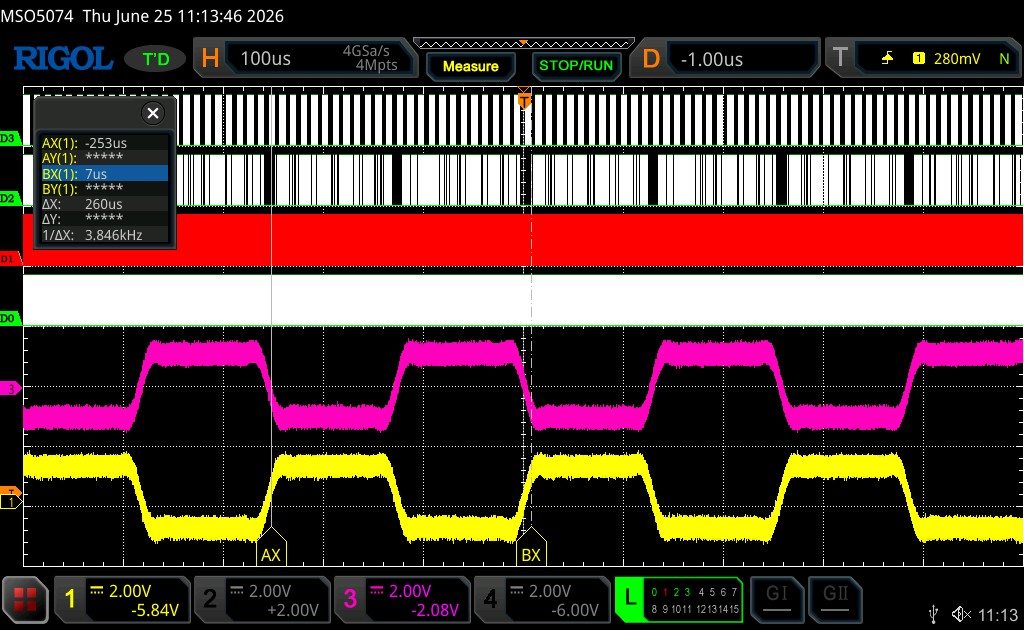
Note that we are generating saturated sinewave.
If you know the reason, let me know in the comments and I will update the guide.
Next, we shall acquire sound data from the microphone.
Stay tuned.
Happy coding 😉
Add Comment