Building upon the fundamentals of polling mode, this next section transitions to using Direct Memory Access (DMA) to handle the data stream. By offloading the continuous transmission of audio samples from the CPU directly to the hardware, this approach eliminates processor overhead and prevents audio stuttering during intensive application tasks.
In this guide, we shall cover the following:
- Introduction.
- STM32CubeMX configuration.
- Firmware development.
- Results.
1. Introduction:
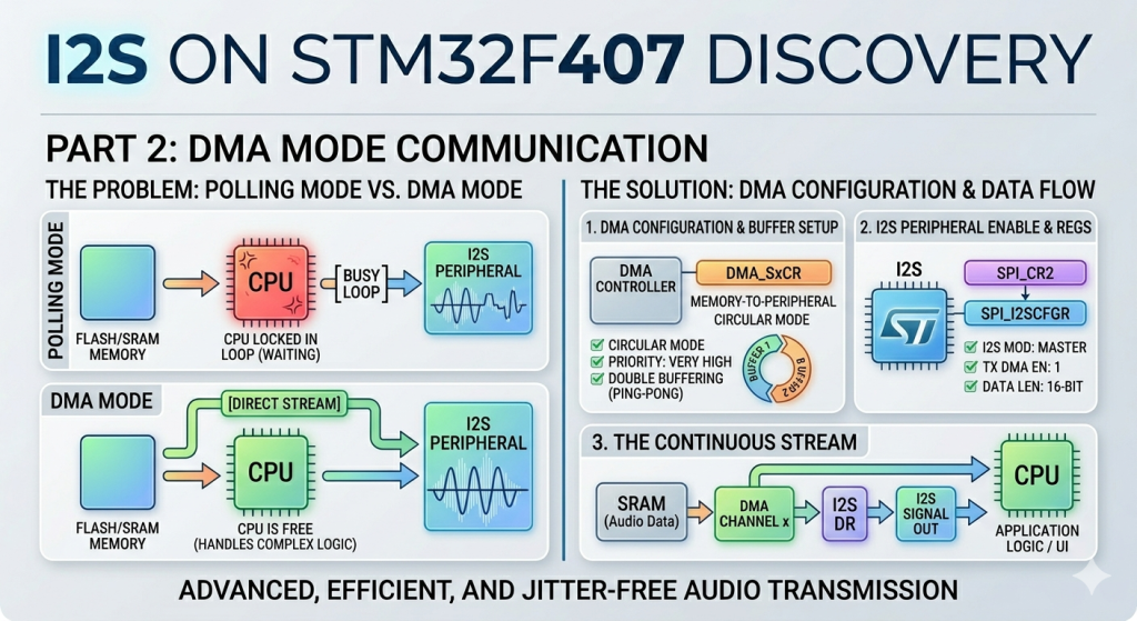
Transitioning from polling mode to Direct Memory Access (DMA) marks a significant upgrade in high-fidelity audio system design on the STM32F407. While polling forces the CPU to constantly wait on hardware flags, DMA acts as an independent hardware bridge that copies audio data blocks directly from your memory arrays to the I2S data register. This automation frees up virtually all processor bandwidth, ensuring jitter-free, continuous playback even when the microcontroller is simultaneously managing complex application logic, display rendering, or user interfaces.
Comparison: Polling Mode vs. DMA Mode
When choosing how to drive the I2S peripheral, balancing performance efficiency against code complexity is key. The table below highlights the operational differences between these two methods:
| Feature | Polling Mode | DMA Mode |
|---|---|---|
| CPU Utilization | Extremely High (~100% during TX). The processor is completely locked in a tight loop checking hardware flags. | Minimal (<1%). The CPU only initiates the transfer and can then sleep or execute other application tasks. |
| Audio Continuity | Prone to glitching. If an interrupt or heavy calculation delays the CPU loop, an audio underrun occurs, causing audible pops. | Rock-solid reliability. Hardware timers and channels guarantee data arrives at the exact sampling interval. |
| Implementation Complexity | Very Simple. Requires only a few lines of code to check the status register (TXE) and write to the data register (DR). | Moderate to High. Requires configuring the DMA multiplexer, streams, channels, memory increments, and circular buffers. |
| Data Handling | Word-by-word (synchronous). | Block-by-block using Ping-Pong or Circular buffers (asynchronous). |
| Ideal Use Case | Quick hardware testing, sensor data validation, or simple non-time-critical sound effects. | Continuous high-quality audio streaming, media players, and real-time audio processing. |
2. STM32CubeMX Configuration:
We shall continue from the previous guide from here.
Open the project in STM32CubeMX and configure I2S as follows:
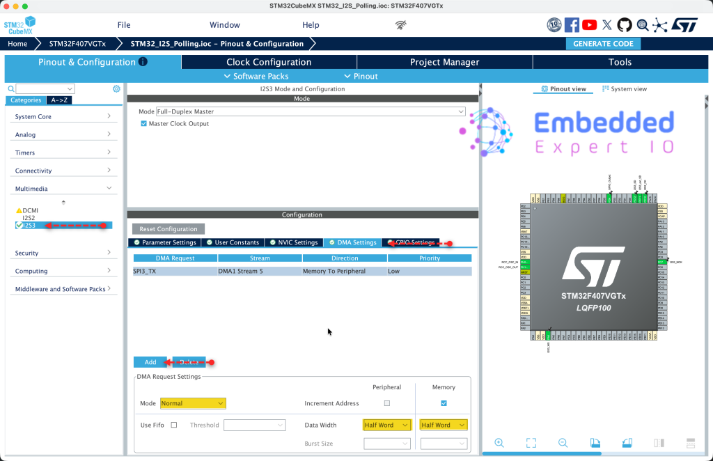
From DMA settings, enable SPI3_TX and set data width to half word for both peripheral and memory as follows:
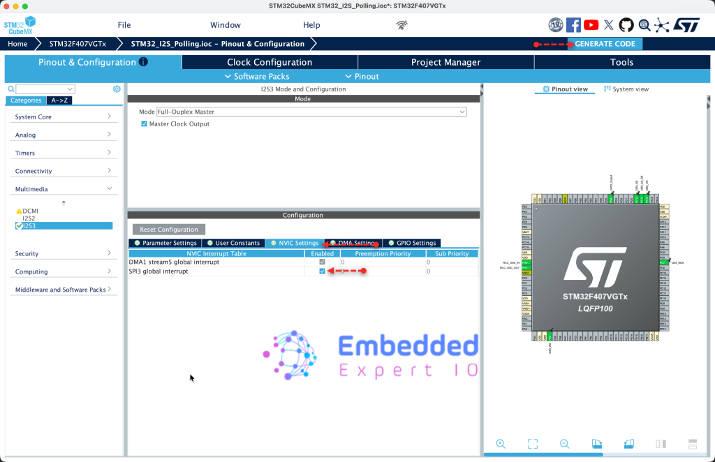
Next, from NVIC Settings, enable SPI3 global interrupt and generate the code as follows:
That all for the STM32CubeMX configuration.
3. Firmware Development:
Open the project in STM32CubeIDE and open main.c
In user code begin PV (Private Variable), declare the following:
volatile uint8_t i2sTx_Completed=0;
The variable will act a flag and be handled in the interrupt to indicate that I2S3 has finished transmission the data using DMA.
In user code begin 0, declare the following function:
void HAL_I2S_TxCpltCallback(I2S_HandleTypeDef *hi2s)
{
	if(hi2s->Instance==SPI3)
	{
		i2sTx_Completed=1;
	}

}
The function HAL_I2S_TxCpltCallback(I2S_HandleTypeDef *hi2s) will be called once the DMA has transferred all the data independent of the mode being circular or normal.
Within the function, check if the interrupt source is SPI3 since I2S3 is controlled by SPI3 peripheral of STM32F407. If the source is SPI3, set i2sTx_Completed to 1 to indicate that the transfer is completed.
In user code begin 3 in while 1 loop:
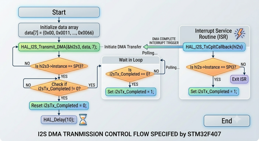
HAL_I2S_Transmit_DMA(&hi2s3, data, 7);

while(i2sTx_Completed==0);
i2sTx_Completed=0;

HAL_Delay(10);
- Start the transfer in DMA mode.
- Wait until the DMA finishes the transfer.
- Delay by 10 ms and repeat.
The flow of the code as follows:
Thats all for the firmware.
Save, build the project and run it as follows:

5. Results:
By probing the pins of MCK, SDK, SD and WS, you should get the following:
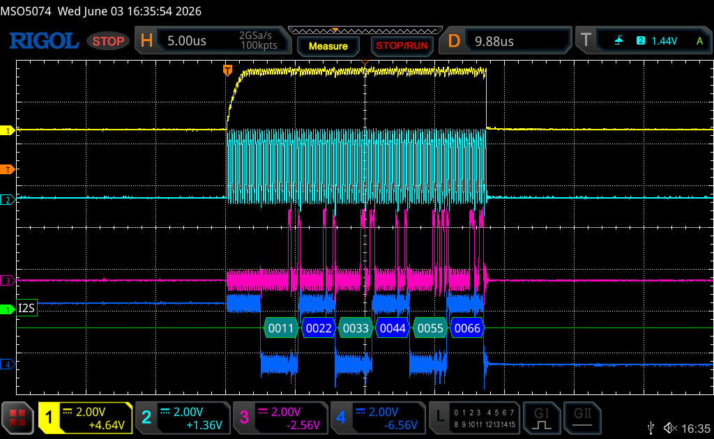
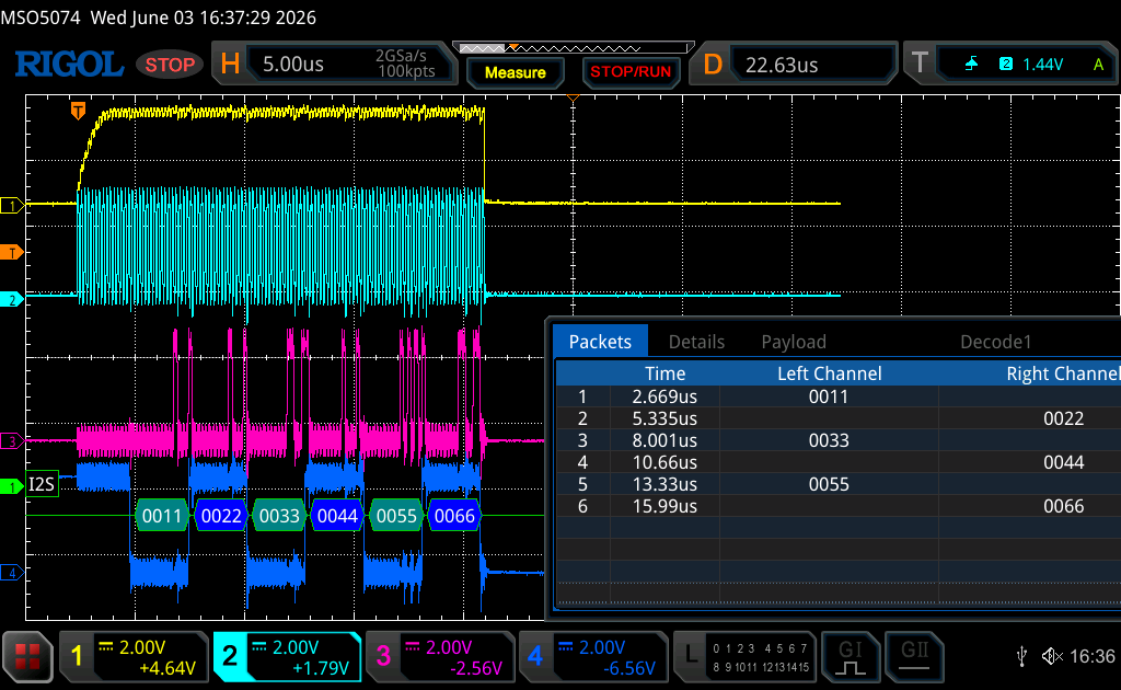
Note: Due to architecture of I2S, the first half word is missing.
In next part, we shall initialize the audio codec device and generate some sounds using I2S.
Stay tuned.
Happy coding 😉
Add Comment