The I2S (Inter-IC Sound) peripheral on the STM32F407 Discovery board provides a dedicated, high-performance synchronous communication interface designed specifically for transmitting digital audio data to external codecs and DACs. This guide covers the foundational steps to understand the underlying I2S protocol architecture, properly configure the microcontroller’s hardware registers, and reliably transmit audio signals using efficient polling-based data transfer.
In this guide, we shall cover the following:
- Introduction.
- STM32CubeMX setup.
- Importing the project to STM32CubeIDE.
- Firmware development.
- Results.
1.1 Introduction:
The Inter-IC Sound (I2S) peripheral on the STM32F407 microcontroller is a specialized, synchronous serial interface designed for high-fidelity digital audio transfer. While sharing physical hardware resources with the standard SPI peripheral, the I2S block is uniquely optimized to handle continuous audio data streams. It implements precise clock synchronization using dedicated internal architecture to feed external components like the CS43L22 Audio DAC found on the STM32F407 Discovery board.
       [ STM32F407 (Master) ]                  [ External DAC / Codec ]
  +------------------------------+            +------------------------+
  |                              |---> CK ---->| Continuous Serial Clock|
  |  I2S Peripheral Engine       |---> WS ---->| Word Select (L/R)      |
  |  (Configured via Registers)  |---> SD ---->| Serial Data Stream     |
  +------------------------------+            +------------------------+
Core Concepts & System Architecture
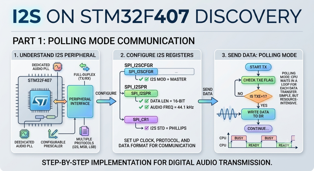
To successfully implement a polling-based driver, the implementation focuses on three core pillars:
- Hardware Interface Architecture: Understanding how the internal clock generation connects to the protocol logic. The peripheral relies on a dedicated audio PLL ($PLLI2S$) to guarantee precise sampling frequencies (such as 44.1 kHz or 48 kHz) while minimizing clock jitter.
- Register Configuration: Setting up communication parameters directly via the hardware abstraction layers or register definitions. Key adjustments are handled in the configuration register (
SPI_I2SCFGR) to set the master mode and selection protocol, and the prescaler register (SPI_I2SPR) to define the exact audio sample rate division. - Polling-Based Firmware Logic: Using a straightforward, synchronous software loop to transmit data. The firmware continuously monitors the Transmit Buffer Empty (
TXE) flag in the status register. Once the flag is set, the CPU immediately writes the next 16-bit audio sample into the Data Register (DR), ensuring an uninterrupted hardware stream without relying on interrupts or DMA.
1.2 Feature Of I2S in STM32F407:
Half-duplex communication (only transmitter or receiver)
• Master or slave operations
• 8-bit programmable linear prescaler to reach accurate audio sample frequencies (from 8 kHz to 192 kHz)
• Data format may be 16-bit, 24-bit or 32-bit
• Packet frame is fixed to 16-bit (16-bit data frame) or 32-bit (16-bit, 24-bit, 32-bit data frame) by audio channel
• Programmable clock polarity (steady state)
• Underrun flag in slave transmission mode, overrun flag in reception mode (master and slave) and Frame Error Flag in reception and transmitter mode (slave only)
• 16-bit register for transmission and reception with one data register for both channel sides
• Supported I 2 S protocols:
– I 2 S Philips standard
– MSB-justified standard (left-justified)
– LSB-justified standard (right-justified)
– PCM standard (with short and long frame synchronization on 16-bit channel frame or 16-bit data frame extended to 32-bit channel frame)
• Data direction is always MSB first
• DMA capability for transmission and reception (16-bit wide)
• Master clock can be output to drive an external audio component. Ratio is fixed at 256 × F S (where F S is the audio sampling frequency)
Block diagram of I2S in STM32G070:

2. STM32CubeMX Setup:
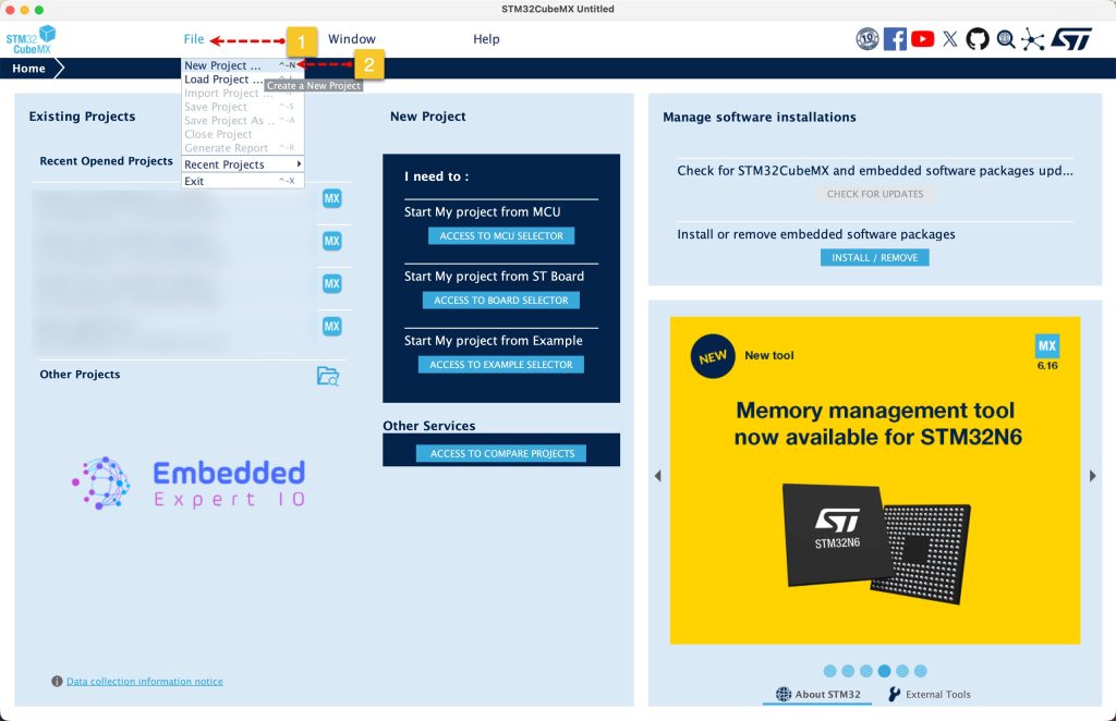
Open STM32CubeMX as start a new project as follows:
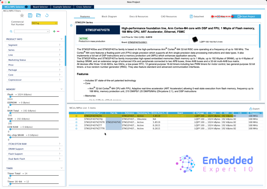
Search for your STM32 MCU, select the MCU and click on Start New Project as follows:
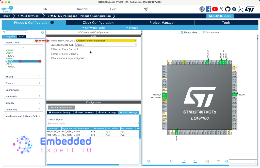
Next, from System Core, RCC, set HSE to Crystal/Ceramic oscillator as follows:
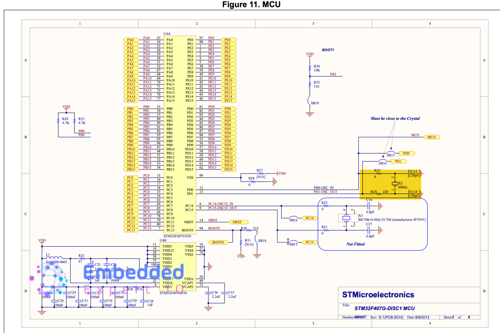
Now, we need to find the frequency of the external oscillator connected to STM32F407 discovery board.
From user manual of STM32F407 Discover, we can find that the crystal oscillator is 8MHz as follows:
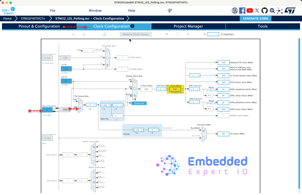
Next, from Clock Configuration, set HSE speed to 8MHz, PLL source to HSE and set the frequency to 1168MHz as follows:
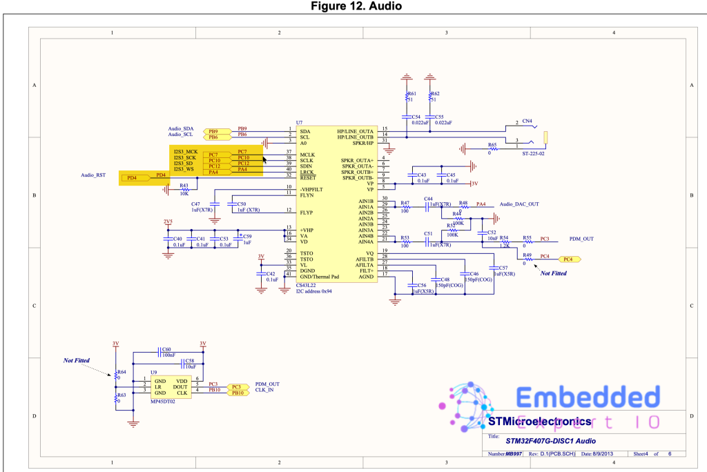
Next, we need to find which pins are connected to the Audio chip. From the user manual of the board, we can find the pins as follows:
- PC7 is I2S3 MCK (Master Clock).
- PC1p is I2S3 SCK (Serial Clock).
- PC12 is I2S3 SD (Serial Data).
- PA4 is I2S3 WS (Word Select).
Also, set PD4 as output to disable the audio chip
Hence, enable the pins as follows:
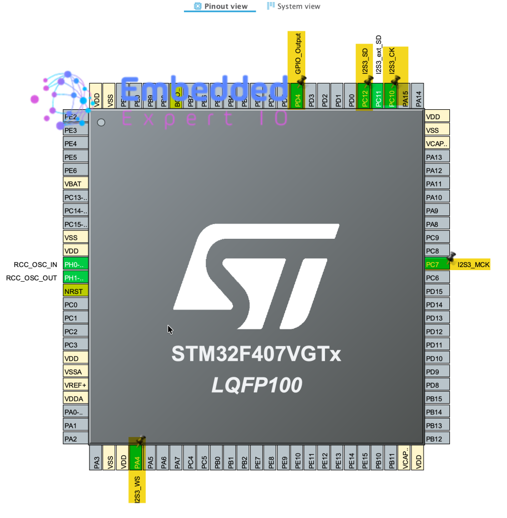
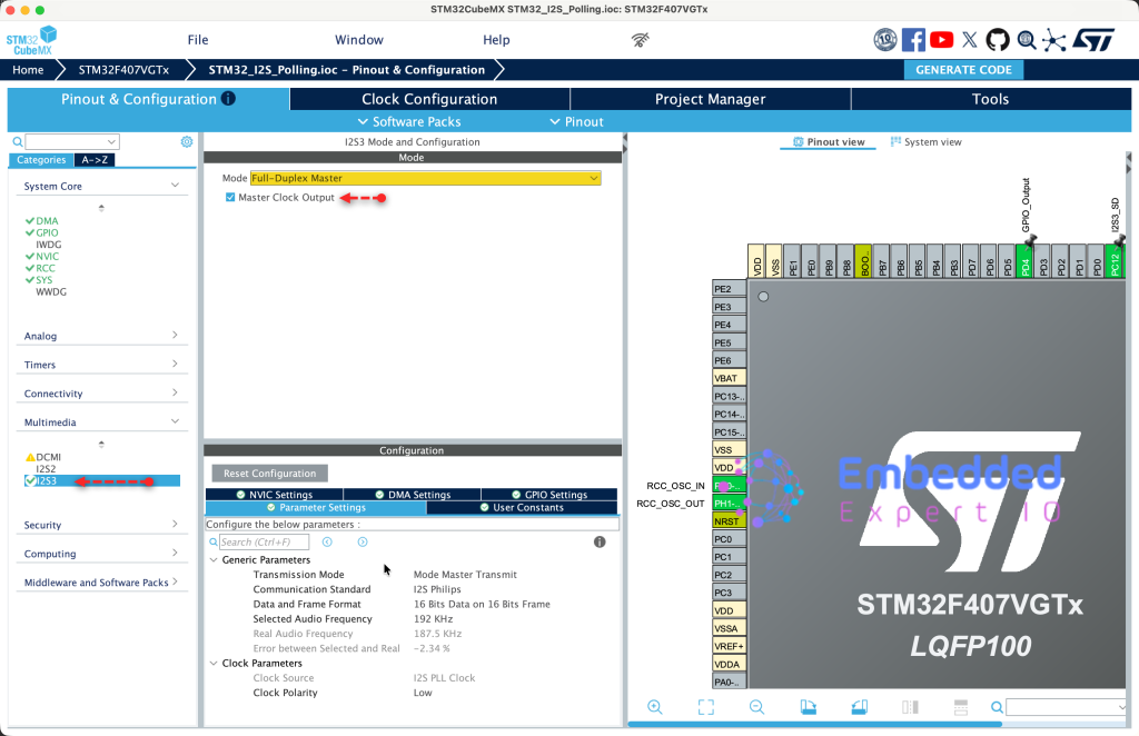
Next, from Multimedia, select I2S3 and enable it as master full duplex with enable master clock as follows:
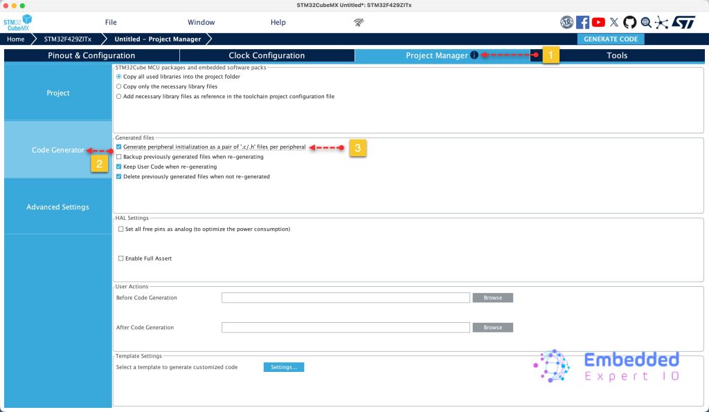
Next, from project tab, select code generation and enable generate peripherals initialization as pair of .c/.h files as follows:
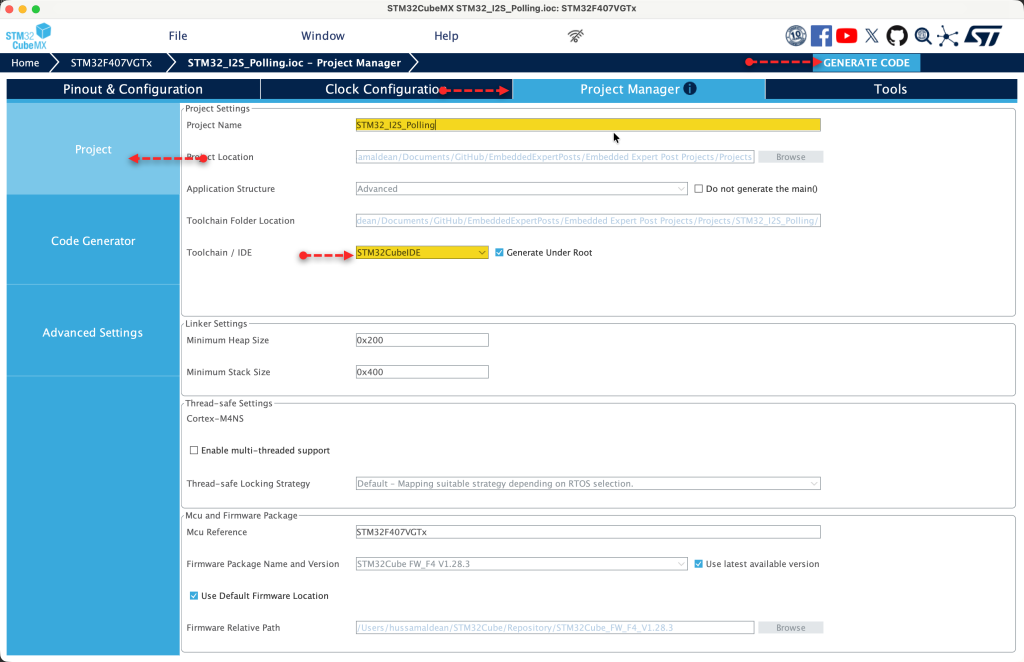
Finally from project, set the destination, give the project a name and set toolchain/IDE to STM32CubeIDE and click on Generate Code as follows:
Thats all for the STM32CubeMX setup.
3. Importing the Project to STM32CubeIDE:
Open STM32CubeIDE, select your workspace and click on Launch.
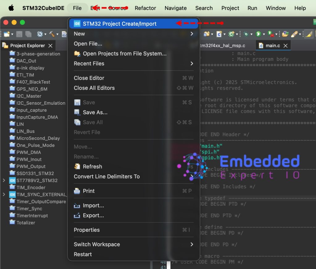
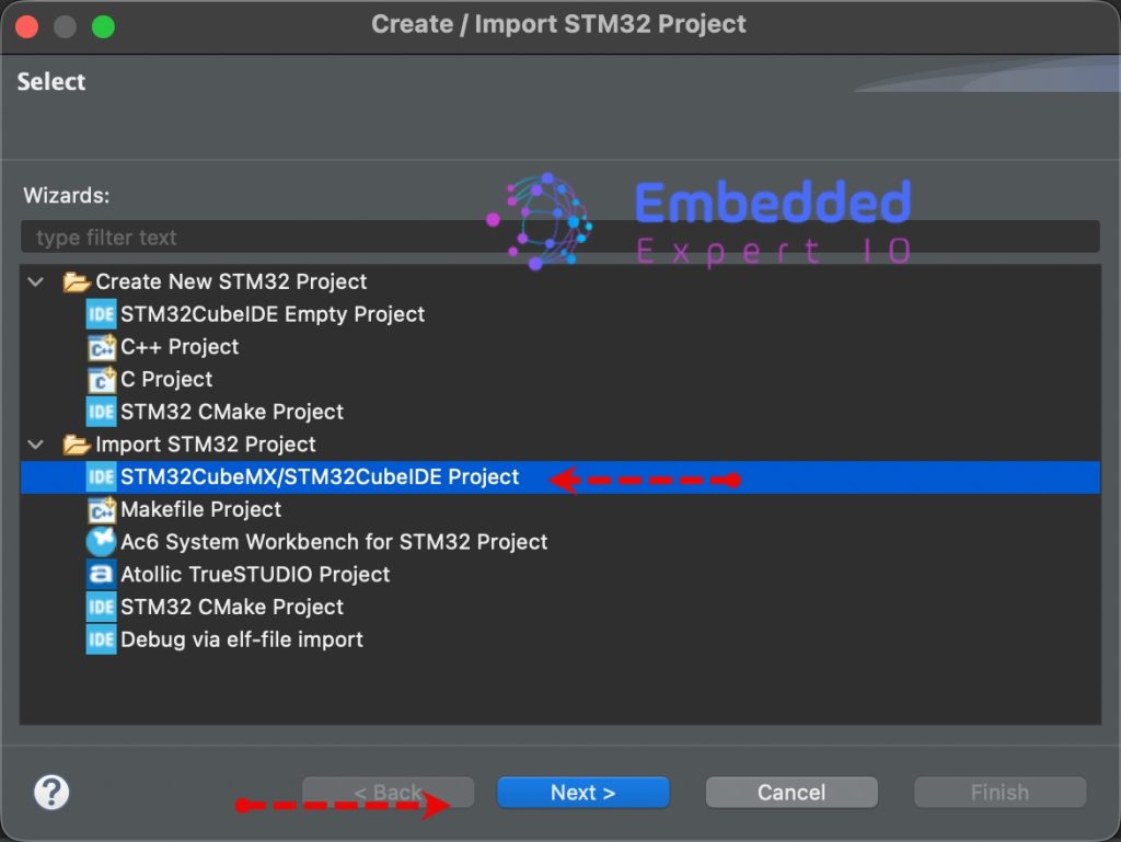
From the IDE, click File and select STM32 Project Create/Import as follows:
Next, from Import STM32 Project, select STM32CubeMX/STM32CubeIDE Project and click on Next as follows:
Next, select the folder that contains the .ioc file and click on Finish as follows:
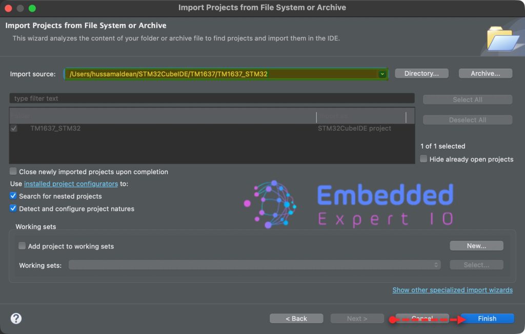
Note: Project name is for reference only.
4. Firmware Development:
We start of in user code begin PV (Private Variable), declare an array with 7 elements as follows:
uint16_t data[7]={0x00,0x0011,0x0022,0x0033,0x0044,0x0055,0x0066};In user code begin code 3 in while 1 loop, we shall keep transmit the I2S data in polling mode as follows:
HAL_I2S_Transmit(&hi2s3, data, 7,100);
HAL_Delay(10);
Give a delay of 10ms for this application.
Thats all for the firmware.
Save, build the project and run it as follows:

5. Results:
By probing the pins of MCK, SDK, SD and WS, you should get the following:
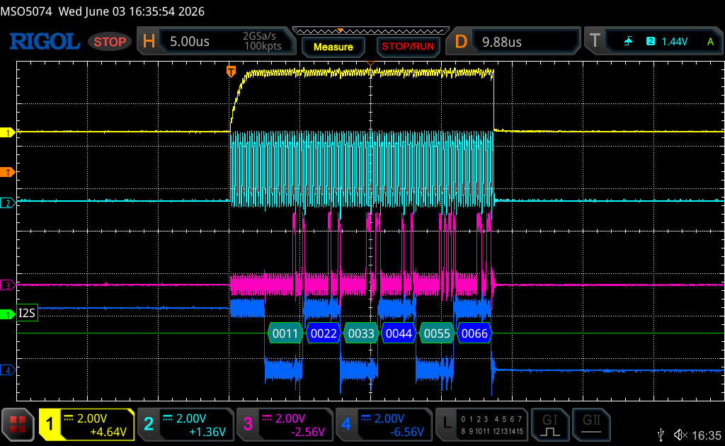
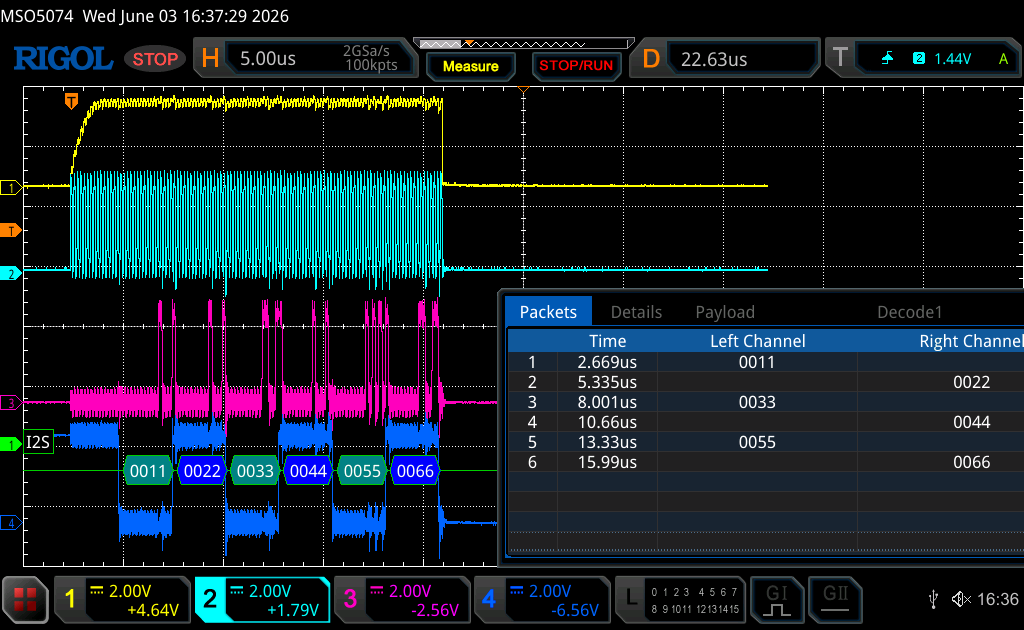
Note: Due to architecture of I2S, the first half word is missing.
Next, we shall use DMA to send the data.
Stay tuned.
Happy coding 😉
Add Comment