Eliminate the CPU bottlenecks caused by blocking transmission loops by shifting to an interrupt-driven UART architecture using Low Layer (LL) drivers. This guide demonstrates how to leverage the Transmit Data Register Empty (TXE) interrupt to background-stream character buffers, allowing your main application logic to run completely uninterrupted while the hardware handles the bit-clocking.
In this guide, we shall cover the following:
- Why interrupt over polling.
- STM32CubeMX setup.
- Firmware development.
- Results.
1. Why Interrupt Over Polling:
The choice between Interrupt-driven execution and Polling is one of the most fundamental architectural decisions in firmware engineering. It represents the trade-off between strict CPU dedication and asynchronous multitasking.
Here is a detailed breakdown of why interrupts are preferred over polling in professional embedded applications:
1. CPU Efficiency and Utilization
- Polling (The Bottleneck): In a polling mode, the CPU is held hostage by a hardware flag. For example, when waiting for a UART byte to transmit at 9600 baud, a single character takes about $1\text{ ms}$. At a $168\text{ MHz}$ CPU clock speed, the processor executes roughly 168,000 completely useless instruction cycles just sitting in a
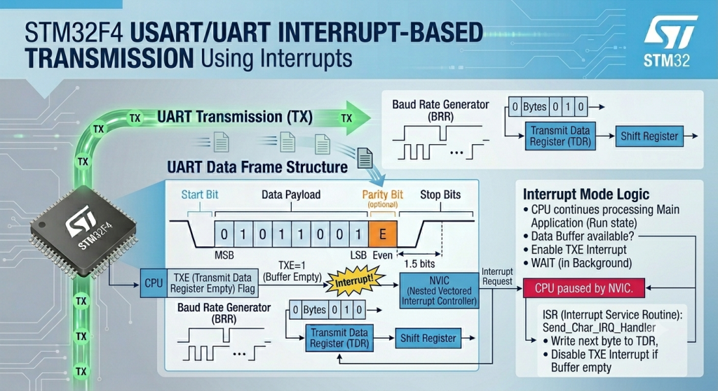
while(!TXE)loop. - Interrupts (The Fix): With interrupts, the CPU continues executing your main application logic (calculating sensor data, updating user interfaces, running state machines). When the hardware buffer becomes empty, the hardware autonomously triggers an execution pause, hands the CPU a single byte to send, and immediately returns control to the main loop. The CPU only spends a fraction of a microsecond handling the hardware event.
2. Power Optimization
- Polling: Because the processor must continuously check a register flag in a tight loop, it must remain running in full-power mode. This quickly drains batteries and generates unnecessary heat.
- Interrupts: Interrupts are the gateway to low-power design. You can put the microcontroller into a deep sleep mode (
Sleep,Stop, orStandby), which completely shuts down the CPU core clock. The core consumes almost zero power until an external event or hardware peripheral trips an interrupt line, instantly waking the CPU to handle the task before it drops back to sleep.
3. Real-Time Responsiveness and Latency
- Polling: If your main loop takes $20\text{ ms}$ to execute due to complex math operations, and a critical sensor changes state at millisecond 2, your application will not know about that change until the loop finishes its cycle $18\text{ ms}$ later. This jitter is unacceptable in safety-critical systems (like motor control or over-current protection).
- Interrupts: The Nested Vectored Interrupt Controller (NVIC) inside the ARM Cortex core watches the hardware lines directly. The exact nanosecond a line switches state, the core halts the main program, preserves the current register stack, and handles the event within a few clock cycles, ensuring deterministic real-time response.
4. Architectural Scalability
- Polling: Polling works well for a single, trivial task. However, as soon as you add a display, multiple communication lines (UART, SPI, $I^2C$), and a couple of user buttons, a polling architecture collapses. One slow peripheral will stall the entire system, causing dropped communication bytes and missed button presses.
- Interrupts: By treating external inputs and peripheral buffers as asynchronous background tasks, your software architecture remains clean, scalable, and modular. It separates your time-critical hardware drivers from your high-level application logic.
Direct Comparison
| Feature | Polling Mode | Interrupt Mode |
| CPU Overhead | High (Stuck in blocking loops) | Low (Executes only on demand) |
| Power Consumption | High (CPU must stay fully active) | Low (Allows sleep/wake cycles) |
| Response Time | Dependent on main loop execution time | Instantaneous (Hardware-triggered) |
| Complexity | Simple to write and debug | Requires ISR management & race-condition care |
| Dropped Data Risk | High if the CPU is busy elsewhere | Very Low due to immediate hardware buffering |
2. STM32CubeMX Setup:
We shall continue from the previous which can be found here.
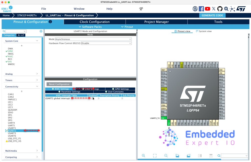
From connectivity, USART2, From NVIC settings, enable USART2 global interrupt as follows:
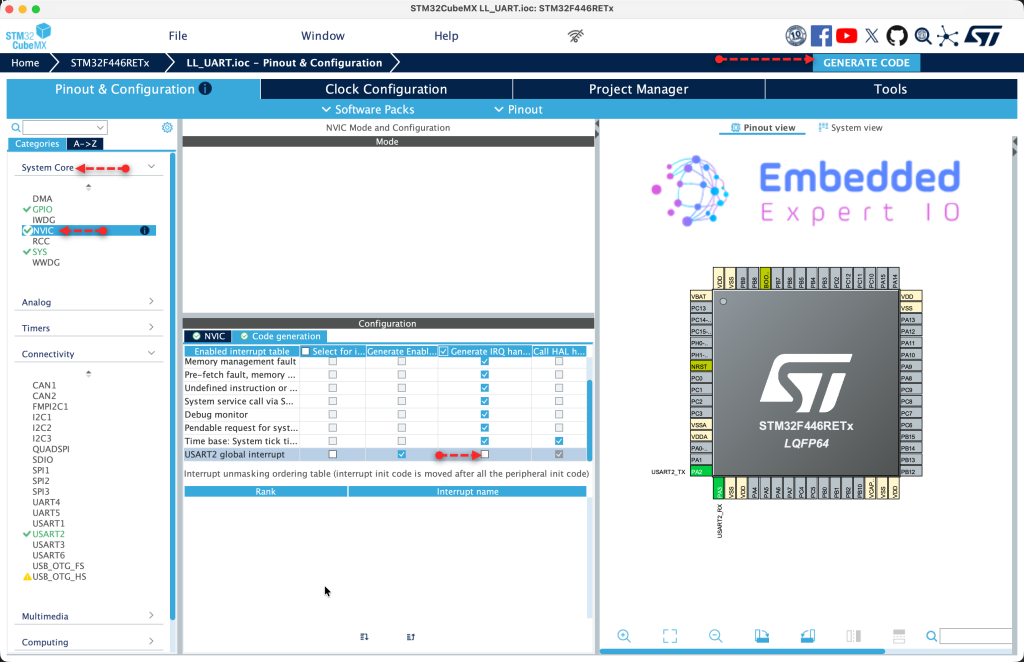
Next, from System Core, NVIC, disable Generate IRQ handler and click Generate Code as follows:
Thats all for STM32CubeMX configuration.
3. Firmware Development:
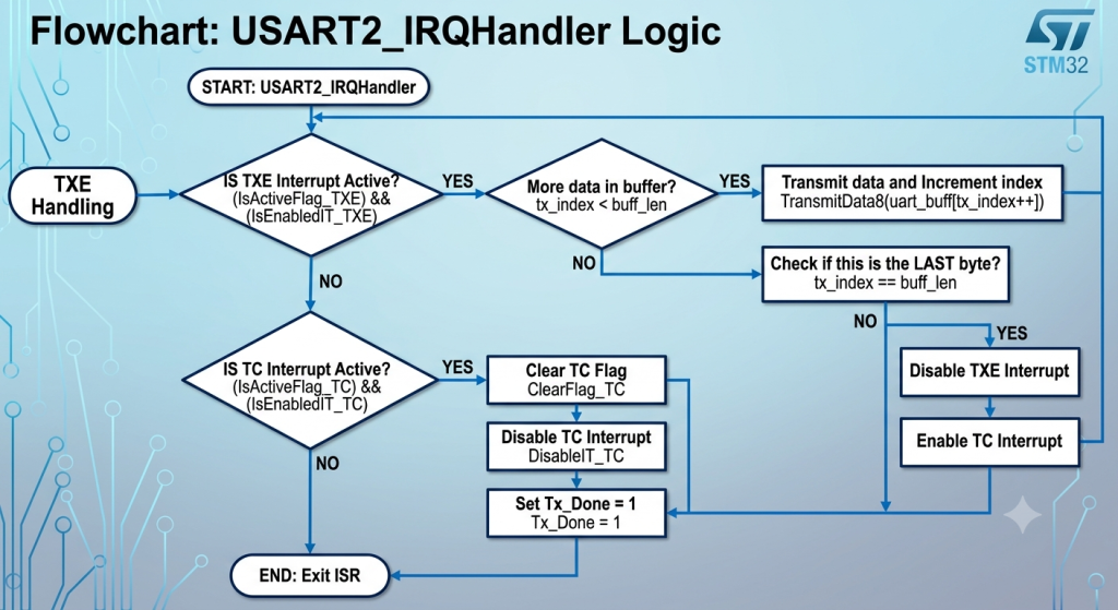
In order to send data using interrupt, the code flow as follows:
In summery:
Phase 1: Transmit Data Register Empty (TXE) Handling
- Step 1: Verify the Source The handler checks if the
TXEhardware flag is active and if theTXEinterrupt is actually enabled. This ensures the handler only processes data when the hardware buffer is truly ready to accept a new byte. - Step 2: Stream Data If the current buffer position (
tx_index) is less than the total message length (buff_len), the next character fromuart_buffis written directly to the data register usingLL_USART_TransmitData8, and the index is post-incremented. - Step 3: Detect the Last Byte Immediately after loading the byte, the handler checks if
tx_indexhas reachedbuff_len. - Step 4: Shift Gears to
TCIf it was the final byte of the buffer, the handler disables theTXEinterrupt (since there is no more data to load) and enables theTC(Transmission Complete) interrupt.
Phase 2: Transmission Complete (TC) Handling
- Step 5: Verify the Wire is Idle The handler checks if the
TCflag is active and if theTCinterrupt is enabled. This flag only trips after the very last byte has completely cleared the internal Shift Register and physical TX pin. - Step 6: Clear and Cleanup Once confirmed, the handler clears the hardware
TCflag usingLL_USART_ClearFlag_TCand disables theTCinterrupt to prevent the handler from firing repeatedly. - Step 7: Flag Completion The application-level status flag
Tx_Doneis set to1, signaling your main program loop that the entire string has been completely and successfully transmitted over the wire.
Next, the firmware.
In user code begin PV, declare the following variables:
uint16_t tx_index;

uint8_t Tx_Done;
Next, USART2 IRQ handler as follows:
void USART2_IRQHandler(void)
{
	if (LL_USART_IsActiveFlag_TXE(USART2) && LL_USART_IsEnabledIT_TXE(USART2))
	{
		if (tx_index < buff_len)
		{
			LL_USART_TransmitData8(USART2, uart_buff[tx_index++]);

			if (tx_index == buff_len)
			{
				LL_USART_DisableIT_TXE(USART2);
				LL_USART_EnableIT_TC(USART2);
			}
		}
	}

	if (LL_USART_IsActiveFlag_TC(USART2) && LL_USART_IsEnabledIT_TC(USART2))
	{
	        LL_USART_ClearFlag_TC(USART2);
	        LL_USART_DisableIT_TC(USART2);
	        Tx_Done = 1;
	}
}
Next, declare a function that will send buffer over UART using interrupt:
void UART_Send_IT(void)
{
	tx_index = 0;
	Tx_Done = 0;

	LL_USART_ClearFlag_TC(USART2);
	LL_USART_EnableIT_TXE(USART2);

}
The function resets the index and tx done flag then clears TC flag and enable TXE (Transfer Buffer Empty).
In user code begin 3 in while 1 loop:
buff_len=sprintf(uart_buff,"Counter Value =%d \r\n",counter++);

UART_Send_IT();
while(Tx_Done==0);
Tx_Done=0;
Create the required string.
Send the data using interrupt and wait for the transmission to end.
Thats all for the firmware.
Save, build and run the project as follows:

4. Results:
Open your favourite terminal application, set the baudrate to 115200 and you should get the following:
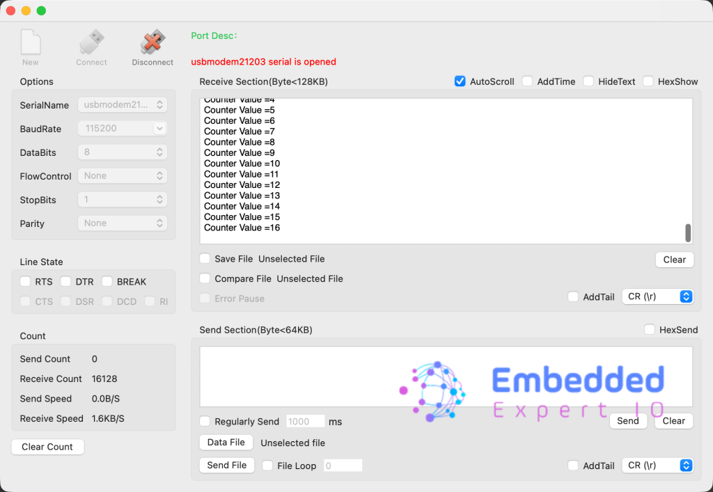
Congratulations, you send the string successfully using interrupt.
You may download the project from here.
Happy coding 😉
Add Comment