In Part 2, we shall develop the core firmware and driver logic required to translate time data into the TM1637’s custom serial protocol. This section focuses on implementing the precise bit-banging timing and segment mapping necessary to display live clock digits on the hardware.
In this guide, we shall cover the following:
- Developing microseconds delay.
- Developing TM1637 firmware.
- main.c code.
- Results.
5. Developing Microseconds Delay:
First, we need to create new source and header files.
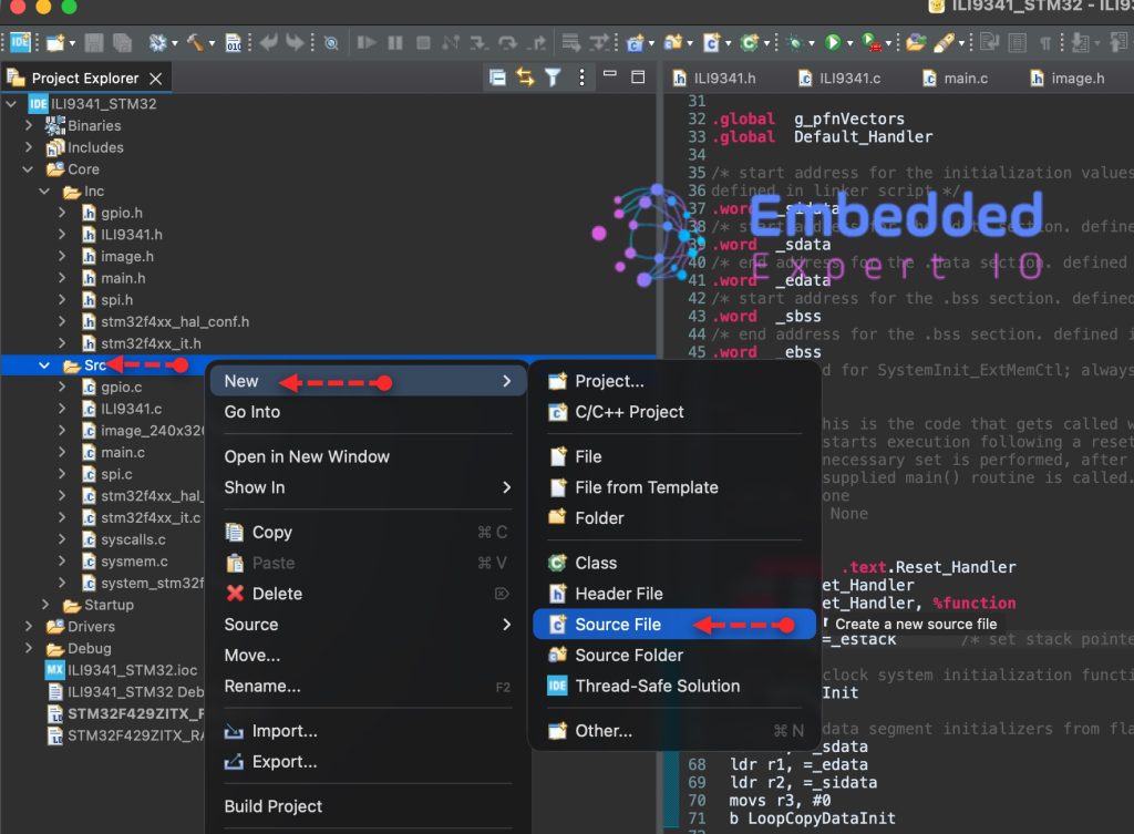
To create Source file, right click on Src folder and add new source file as following:
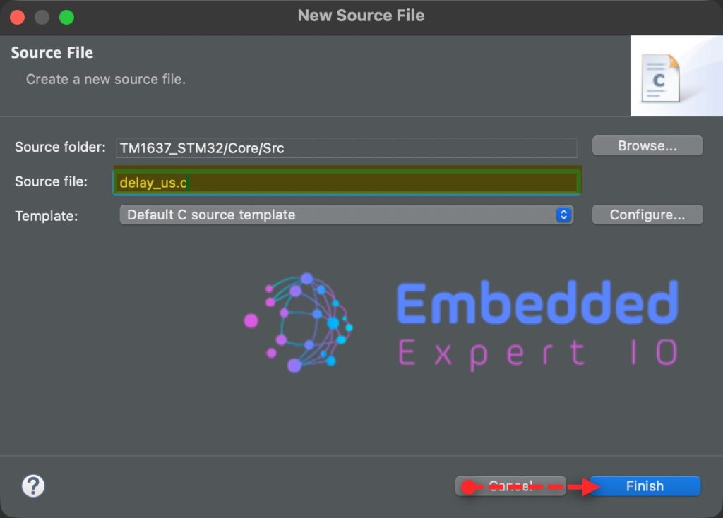
Give a name for the source file, we shall name it as delay_us.c as following:
In similar manner, right click on Inc folder and add new header file with name of delay_us.h as follows:

Open delay_us.h header file. We start by including the following:
#include "tim.h"
#include "stdint.h"
Next, declare the following two functions:
void delay_us_start(void);
void delay_us(uint32_t us);
That all for the header file.
Next, open delay_us.c source file. Include the following header file as follows:
#include "delay_us.h"
Next, the functions:
void delay_us_start(void)
{
	HAL_TIM_Base_Start(&htim2);
}


void delay_us(uint32_t us)
{
	__HAL_TIM_SET_COUNTER(&htim2,0);  // set the counter value a 0
	while ((uint32_t)__HAL_TIM_GET_COUNTER(&htim2) < us);  // wait for the counter to reach the us input in the p
}
For more details how these functions have been developed, please refer to this guide.
6. Developing TM1637 Firmware:
First, we need to create new source and header files.
To create Source file, right click on Src folder and add new source file as following:
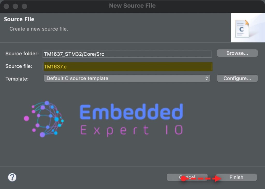
Give a name for the source file, we shall name it as TM1637.c as following:
In similar manner, right click on Inc folder and add new header file with name of TM1637.h as follows:

In the header file, we start by including the following header files:
#include "main.h"
#include "gpio.h"
#include "delay_us.h"
Next, declare the following function:
void tm1637Init(void);
It is a one-time configuration step that prepares the TM1637 to accept single-digit (fixed-address) writes.
Next,
void tm1637SetDigit(uint8_t position, uint8_t value, uint8_t dot);
This is a function prototype that declares a function used to update one digit on a 4-digit TM1637 display.
position(0–3): selects which digit to updatevalue(0–15): selects the segment pattern (0–9, A–F)dot(0 or 1): turns the decimal point on or off
Next,
void tm1637SetBrightness(char brightness);
This function manages the internal Pulse Width Modulation (PWM) of the TM1637 chip to control how much current flows through the LEDs.
Last function:
void tm1637SetColon(uint8_t state);
This is a function prototype used to control the colon (:) indicator on a TM1637 clock-style display.
Thats all for the header file.
Next, open TM1637.c source file.
We start by including the following header file:
#include "TM1637.h"
First, declare a buffer to hold the digit to be displayed as follows:
uint8_t displayBuffer[4]={0};Then, declare segment map as follows:
const char segmentMap[] = {
    0x3f, 0x06, 0x5b, 0x4f, 0x66, 0x6d, 0x7d, 0x07, // 0-7
    0x7f, 0x6f, 0x77, 0x7c, 0x39, 0x5e, 0x79, 0x71, // 8-9, A-F
    0x00
};
Next, declare macros to handle the state of CLK and DIO pins as follows:
#define _tm1637ClkHigh() HAL_GPIO_WritePin(CLK_GPIO_Port,CLK_Pin,GPIO_PIN_SET);
#define _tm1637ClkLow()  HAL_GPIO_WritePin(CLK_GPIO_Port,CLK_Pin,GPIO_PIN_RESET);

#define _tm1637DioHigh() HAL_GPIO_WritePin(DIO_GPIO_Port,DIO_Pin,GPIO_PIN_SET);
#define _tm1637DioLow()  HAL_GPIO_WritePin(DIO_GPIO_Port,DIO_Pin,GPIO_PIN_RESET);
Since my module has time separator rather than decimal points, I defined the following statement to handle this:
#define COLON_POS 1 // or 2 depending on your module
Next, declare the function to handle the delay in uS for the module as follows:
static void _tm1637DelayUsec(unsigned int i)
{
delay_us(i);
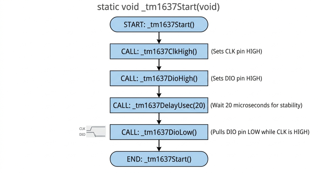
}Next, for start condition:
static void _tm1637Start(void)
{
    _tm1637ClkHigh();
    _tm1637DioHigh();
    _tm1637DelayUsec(20);
    _tm1637DioLow();
}
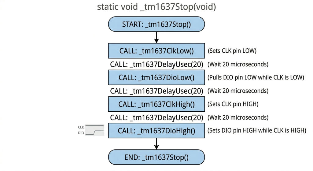
Next, stop condition:
static void _tm1637Stop(void)
{
    _tm1637ClkLow();
    _tm1637DelayUsec(20);
    _tm1637DioLow();
    _tm1637DelayUsec(20);
    _tm1637ClkHigh();
    _tm1637DelayUsec(20);
    _tm1637DioHigh();
}
Next, reading the results:
static void _tm1637ReadResult(void)
{
    _tm1637ClkLow();
    _tm1637DelayUsec(50);
    // while (dio); // We're cheating here and not actually reading back the response.
    _tm1637ClkHigh();
    _tm1637DelayUsec(20);
    _tm1637ClkLow();
}
This is just to follow the requirement and wast a little bit of time.
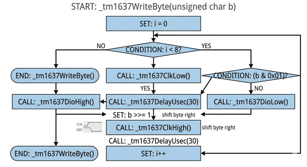
Next, write single byte to the module:
static void _tm1637WriteByte(unsigned char b)
{
    for (int i = 0; i < 8; ++i) {
        _tm1637ClkLow();
        if (b & 0x01) {
            _tm1637DioHigh();
        }
        else {
            _tm1637DioLow();
        }
        _tm1637DelayUsec(30);
        b >>= 1;
        _tm1637ClkHigh();
        _tm1637DelayUsec(30);
    }
}
Next, for the initialization of the module:
void tm1637Init(void)
{
    _tm1637Start();
    _tm1637WriteByte(0x44); // fixed address mode
    _tm1637ReadResult();
    _tm1637Stop();
}
Next, write to a digit:
void tm1637SetDigit(uint8_t position, uint8_t value, uint8_t dot)
{
    if (position > 3 || value > 15) return;

    uint8_t seg = segmentMap[value];

    if (dot)
        seg |= 0x80;

    displayBuffer[position] = seg;

    // Write single digit
    _tm1637Start();
    _tm1637WriteByte(0xC0 | position);
    _tm1637ReadResult();

    _tm1637WriteByte(seg);
    _tm1637ReadResult();

    _tm1637Stop();
}
Set the brightness:
void tm1637SetBrightness(char brightness)
{
    // Brightness command:
    // 1000 0XXX = display off
    // 1000 1BBB = display on, brightness 0-7
    // X = don't care
    // B = brightness
    _tm1637Start();
    _tm1637WriteByte(0x87 + brightness);
    _tm1637ReadResult();
    _tm1637Stop();
}
This function for displaying the separator as follows:
void tm1637SetColon(uint8_t state)
{
    if (state)
        displayBuffer[COLON_POS] |= 0x80;
    else
        displayBuffer[COLON_POS] &= ~0x80;

    // Rewrite only that digit
    _tm1637Start();
    _tm1637WriteByte(0xC0 | COLON_POS);
    _tm1637ReadResult();

    _tm1637WriteByte(displayBuffer[COLON_POS]);
    _tm1637ReadResult();

    _tm1637Stop();
}
This function will maintain the current value and update the separator only.
Thats all for the firmware.
7. Main.c Code:
Open main.c.
In user code includes, include the following header files:
#include "TM1637.h"
#include "delay_us.h"
In user code begin PV, declare the following variables to display the time:
uint8_t hours = 12;
uint8_t minutes = 0;

uint8_t colonState = 0;

uint32_t lastTick = 0;
In user code begin 0:
void updateDisplay(void)
{
    tm1637SetDigit(0, hours / 10, 0);
    tm1637SetDigit(1, hours % 10, colonState); // separator here
    tm1637SetDigit(2, minutes / 10, 0);
    tm1637SetDigit(3, minutes % 10, 0);
}
In user code begin 2, start the microsecond timer as follows:
delay_us_start();
Initialize the display:
tm1637Init();
Set the brightness:
tm1637SetBrightness(5);
In user code begin 3 in while 1 loop:
if (HAL_GetTick() - lastTick >= 1000)
{
  lastTick = HAL_GetTick();

  // Toggle colon
  colonState ^= 1;

  // Increment time
  minutes++;

  if (minutes >= 60)
  {
    minutes = 0;
    hours++;

    if (hours >= 24)
      hours = 0;
  }

  updateDisplay();
}
Thats all for the guide.
Save, build the project and run it as follows:

You may download the code below:
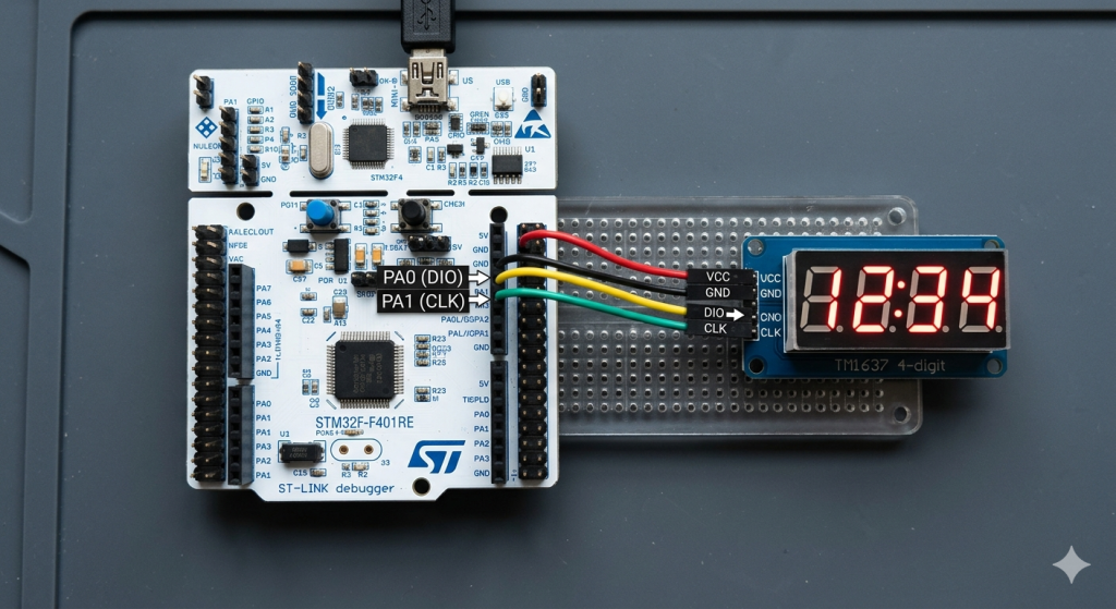
8. Results:
You should get the following:
Please note that in the demo, I am increasing the minutes each second for the demo purposes.
Happy coding 😉
Add Comment