Timers in STM32 microcontrollers are essential for generating precise delays, measuring time intervals, and controlling periodic events. This guide focuses on using STM32 timers to achieve accurate microsecond delays, ensuring precise timing in embedded applications.
In this guide, we shall cover the following:
- Introduction.
- Timer setup.
- Delay development.
- Results.
1. Introduction:
Timers are a fundamental feature of STM32 microcontrollers, providing precise timekeeping, delay generation, and event synchronization. In embedded systems, accurate timing is essential for various applications, including signal processing, communication protocols, and real-time control. Unlike simple delay loops, which depend on CPU execution speed and can be affected by compiler optimizations, hardware timers offer a reliable and efficient way to generate precise delays.
This guide focuses on achieving microsecond-level delays using STM32 timers. STM32 microcontrollers come equipped with multiple timer peripherals, each designed for specific tasks. These include general-purpose timers, advanced timers for motor control, and basic timers used for timebase generation. By configuring these timers appropriately, developers can generate precise delays without affecting other tasks running on the microcontroller.
Microsecond delays are particularly useful in applications that require precise timing, such as pulse generation, duty cycle control, and high-speed data acquisition. For instance, communication protocols like UART, SPI, and I2C require accurate timing to ensure proper data transmission. Additionally, generating PWM signals with fine resolution depends on the ability to create precise delays at the microsecond level.
To achieve a microsecond delay, an STM32 timer can be configured with an appropriate clock source, prescaler, and counter settings. The microcontroller’s system clock, which operates at several megahertz, serves as the base for timer operations. By dividing this clock through a prescaler, the timer counts at a controlled rate, allowing the generation of delays as short as a single microsecond.
Several approaches can be used to implement a microsecond delay with timers. One common method involves configuring a general-purpose timer in a one-pulse mode or using an interrupt to signal when a delay has elapsed. Another approach is polling the timer’s counter value until the desired delay is reached. These methods ensure that the delay is consistent and independent of CPU execution speed.
In this guide, we will explore different ways to implement microsecond delays using STM32 timers. We will discuss the timer architecture, how to configure the timer registers, and how to achieve accurate timing using both polling and interrupt-based approaches. Practical examples will demonstrate how to apply these techniques in real-world embedded applications.
Understanding STM32 timers and their capabilities allows developers to create precise, efficient, and reliable timing mechanisms. By leveraging hardware timers instead of software delays, applications can achieve better performance, lower power consumption, and improved accuracy. This guide aims to provide a solid foundation for working with STM32 timers to generate microsecond delays, enabling more advanced and precise timing control in embedded projects.
2. Timer Setup:
Open STM32CubeIDE after selecting the workspace and create new project as following:

Select the MCU:

Give the project a name:
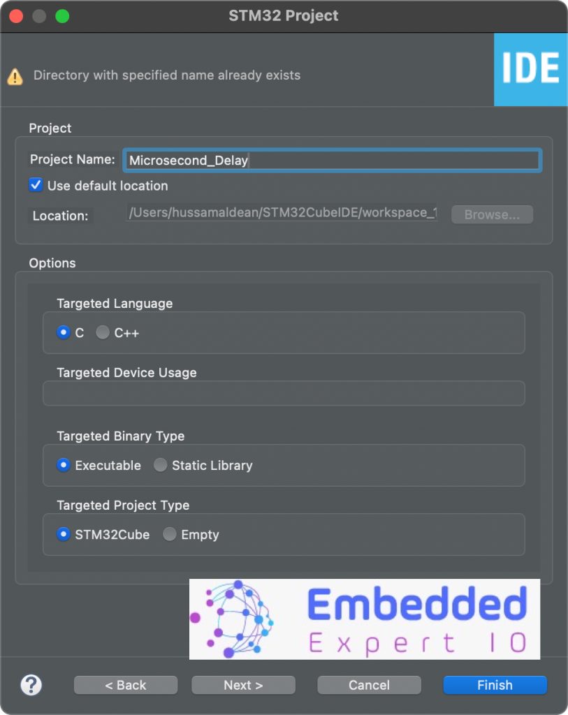
Click on finish.
Next, STM32CubeMX Window will appear.
From the window, select Clock Configuration as following:
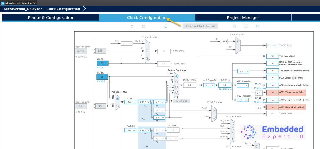
Notice timers clock. Since STM32F4 has default frequency of 16MHz, hence timers frequency is 16MHz.
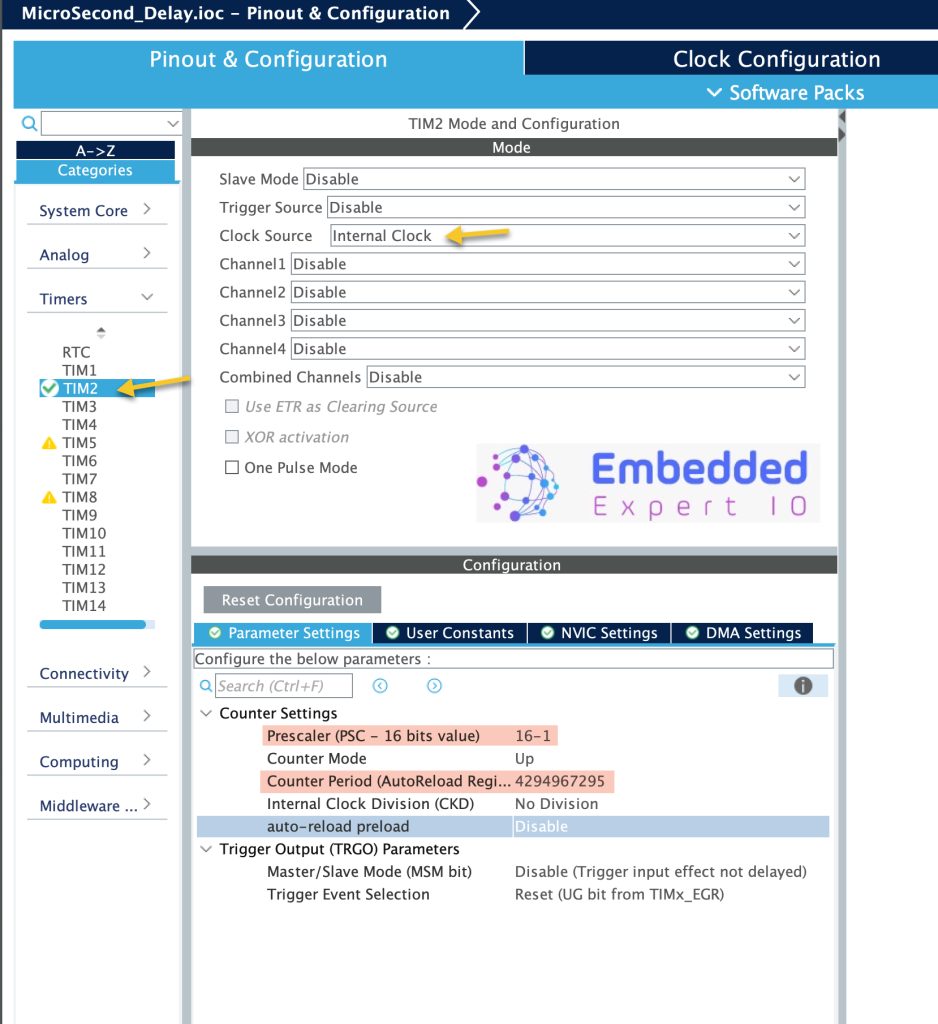
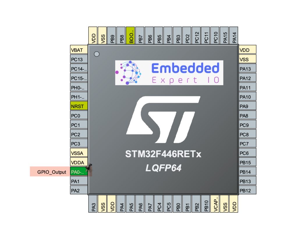
Next, from Pinout and Configuration, select timers, then the desired timer (TIM2 in the case) as following:
- Set Clock source to internal.
- Set PSC to 16-1, this will give timer frequency of 1MHz.
- Set the period to maximum (4,294,967,295 for 32-bit or 65,535 for 16-bit timer).
Keep the rest of the setting as is.
Also, enable a pin output, in this guide, it shall be PA0:
Thats all for the configuration. Save the project and this will generate the project.
3. Delay Development:
In main.c in user code begin 0 declare the delay function as following:
void delay_us (uint32_t us)
{
	__HAL_TIM_SET_COUNTER(&htim2,0);  // set the counter value a 0
	while ((uint32_t)__HAL_TIM_GET_COUNTER(&htim2) < us);  // wait for the counter to reach the us input in the parameter
}
The function shall take the amount to delay and returns nothing.
In the function, first, reset the counter. Then, wait using while loop until the counter value is less than desired delay. Once the value reached, the function will exit.
In user code begin 1 in main function, start the timer in base mode as following:
HAL_TIM_Base_Start(&htim2);
In user code begin 3 in while 1 loop:
	  HAL_GPIO_TogglePin(GPIOA, GPIO_PIN_0);
	  delay_us(10);
We shall simply, toggle the pin each 10 microseconds.
Save the project, build and run it on your board as following:

That all for the driver.
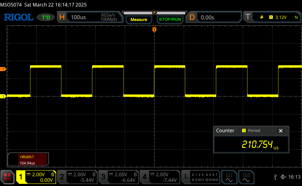
4. Results:
Using either logic analyzer or oscilloscopes and probe the pin.
You should get the following:
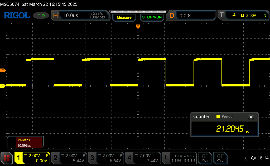
For 100uS:
Feel free to optimize to delay function.
Happy coding 😉
Add Comment