This guide demonstrates how to interface an STM32 microcontroller with the TM1637 display module to create a real-time digital clock, focusing on implementing the custom two-wire serial protocol and effective time formatting. In Part 1, we shall cover the technical features of the module, the physical hardware connections, and the essential STM32CubeMX peripheral configuration.
In this guide, we shall cover the following:
- Introduction.
- Hardware setup
- STM32CubeMX configuration.
- Importing the project to STM32CubeIDE.
1. Introduction:
In the world of embedded systems, visual feedback is the primary bridge between machine logic and human understanding. While modern high-resolution TFTs and OLEDs offer stunning graphics, the classic 7-segment displayremains the gold standard for clarity, high contrast, and efficiency in sunlight or high-glare environments. At the heart of many these affordable, 4-digit modules lies the TM1637—a dedicated LED drive control circuit that has revolutionized how we interface with numeric displays.
Traditionally, driving a 4-digit 7-segment display was a resource-heavy task. To light up all four digits, a microcontroller would typically need to manage at least 12 GPIO pins and run a constant background refresh loop (multiplexing) to keep the LEDs from flickering. This not only consumes precious CPU cycles but also creates a “rat’s nest” of wiring on a breadboard. The TM1637 solves this by integrating an internal latch, data decoder, and LED high-voltage drive circuit, allowing you to control the entire display using only two digital pins.
Technical Architecture and “Pseudo-I2C”
What makes the TM1637 particularly interesting for engineers is its unique communication protocol. While it utilizes a two-wire interface consisting of Clock (CLK) and Data (DIO), it is not a standard I2C device. It lacks a hardware slave address, meaning you cannot share the same bus with other $I^2C$ sensors. Instead, it uses a simplified serial start/stop bit mechanism that is highly robust against timing jitters. By offloading the constant scanning of segments to the TM1637’s internal silicon, the STM32 is freed up to perform complex calculations, sensor sampling, or RTOS task management without the display brightness ever wavering.
Comprehensive Feature Set
- Integrated Segment/Grid Management: The chip handles all the logic for common-anode LED configurations, providing consistent current to each segment for uniform brightness.
- Built-in Key Scanning: A often-overlooked feature is its ability to scan a matrix of up to 16 keys. This makes it a complete “User Interface” chip—capable of both showing the time and reading the buttons used to set it.
- Dynamic Dimming (PWM): The TM1637 features an 8-level pulse width modulation controller. This allows for “Night Mode” or “Power Saving” features where the display can be dimmed via software commands without adding any external components.
- Low-Power Operation: Designed with power efficiency in mind, the chip consumes minimal current when the display is cleared, making it suitable for battery-backed applications where the STM32 might enter sleep modes.
Real-World Versatility
Because of its ruggedness and simplicity, the TM1637 is found everywhere from the dashboard of an industrial temperature controller to the simple countdown timer on a microwave. Its ability to work across a wide voltage range (typically 3.3V to 5V) makes it perfectly compatible with the 3.3V logic levels of the STM32F4 series while still providing enough “punch” to drive bright red or green LEDs.
The Learning Path
In this guide, we aren’t just looking at how to make numbers appear; we are exploring the architecture of a custom serial protocol. By implementing a TM1637 driver on an STM32, you will gain a deeper understanding of bit-banging techniques, timing diagrams, and the importance of efficient peripheral management. Whether you are building a professional-grade digital clock, a countdown timer for a laboratory experiment, or a diagnostic readout for your latest robotics project, the TM1637 is an essential tool in your hardware repertoire.
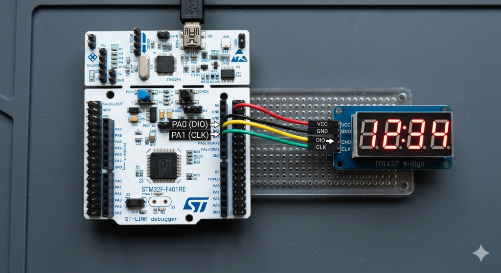
2. Hardware Setup:
The hardware setup as follows:
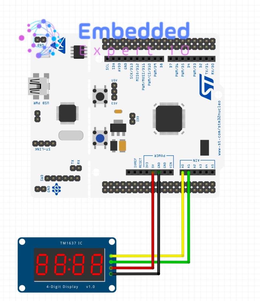
| TM1637 | STM32F411 Nucleo-64 |
| Vcc | 5V |
| GND | GND |
| DIO | PA1 (A1 of Arduino Connector) |
| CLK | PA0 (A0 of Arduino Connector) |
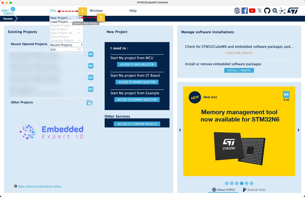
3. STM32CubeMX Setup:
Open STM32CubeMX as start a new project as follows:
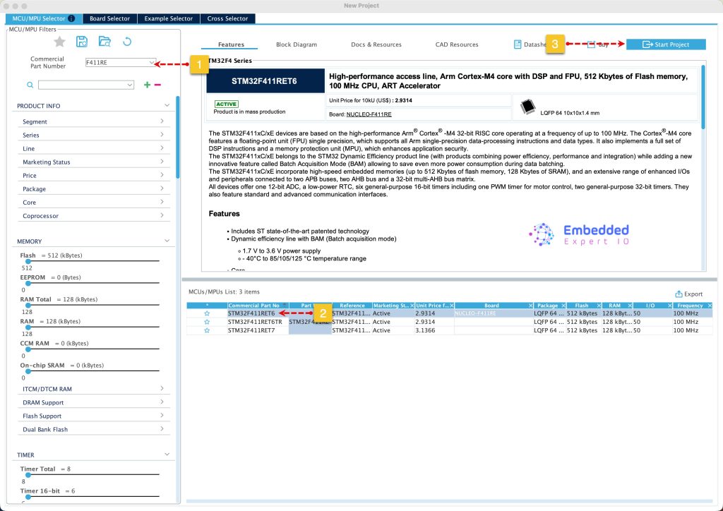
Search for your STM32 MCU, select the MCU and click on Start New Project as follows:
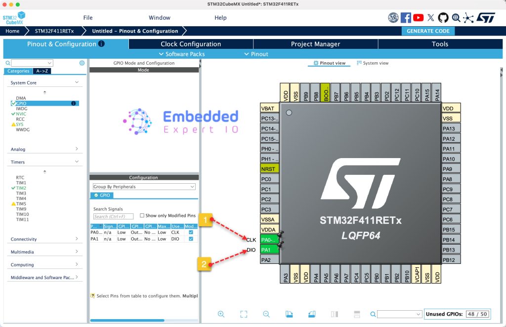
Next, from Pinout View, set PA0 and PA1 as output and give them label with name of CLK and DIO respectively as follows:
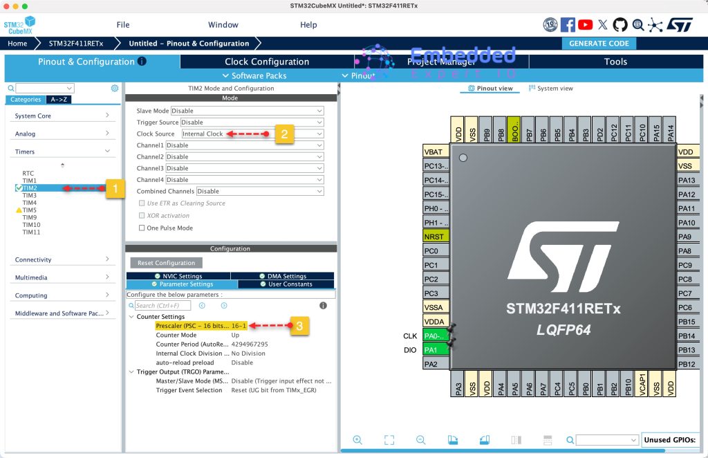
Next, we need to configure a timer to generate microseconds delays to bit-bang the protocol. From Timers, select TIM2 and configure it as following:
- Set Clock source to internal.
- Set PSC to 16-1, this will give timer frequency of 1MHz.
- Set the period to maximum (4,294,967,295 for 32-bit or 65,535 for 16-bit timer).
Keep the rest of the setting as is.
For more informations why these parameters, please refer to this guide.
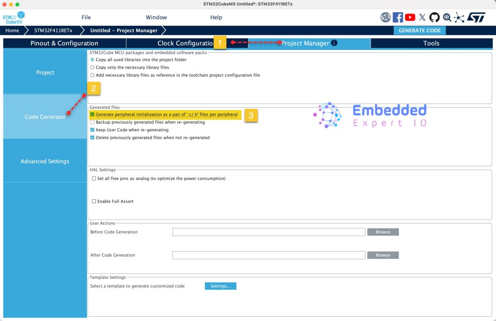
Next, from Project Manager tab, Code generation tab, enable generate peripherals initialization as pair of c/h files
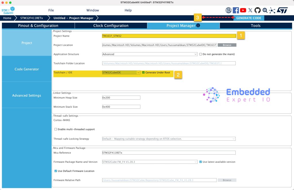
Next, from Project tab in Project Manager, give the project a name, set the Toolchain/IDE to STM32CubeIDE and click on Generate Code as follows:
Thats all for the configuration.
4. Importing the Project to STM32CubeIDE:
Open STM32CubeIDE, select your workspace and click on Launch.
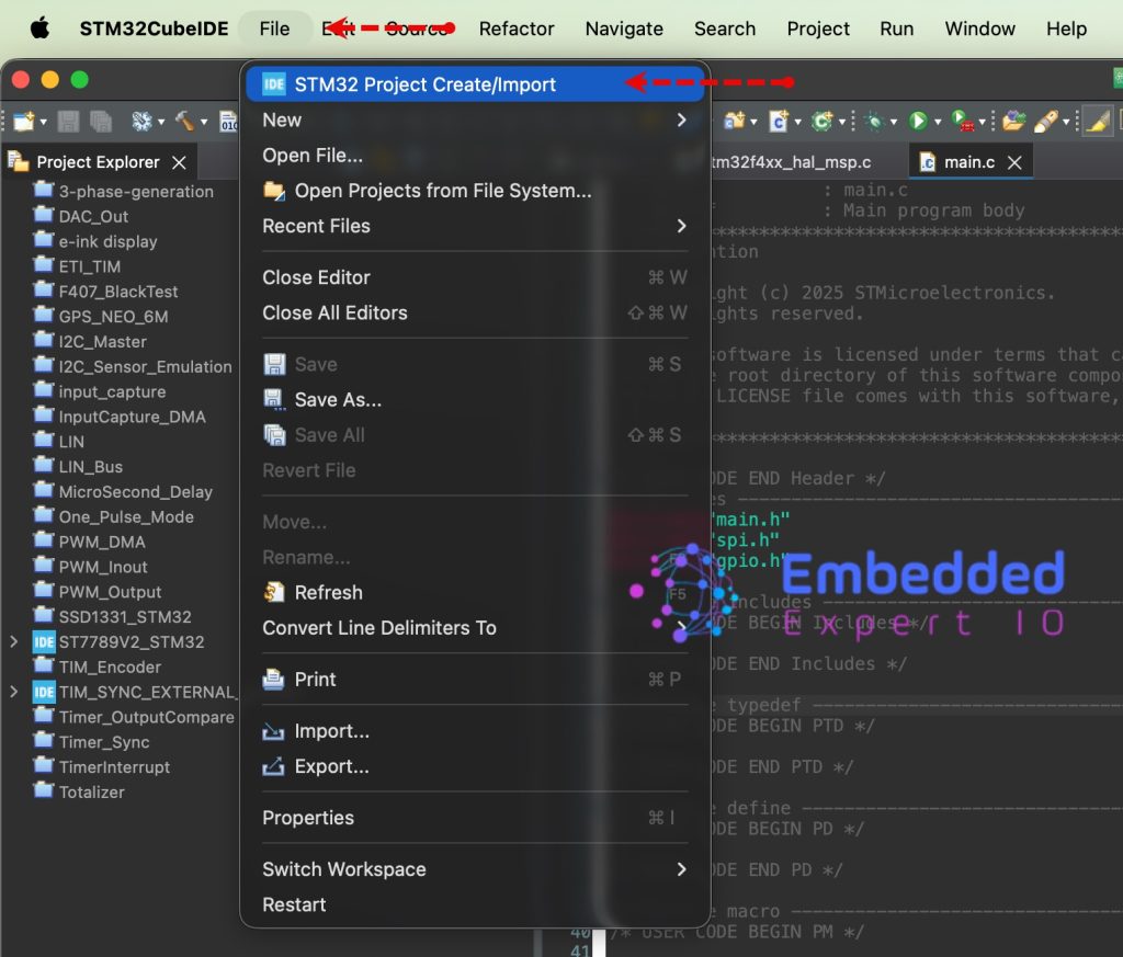
From the IDE, click File and select STM32 Project Create/Import as follows:
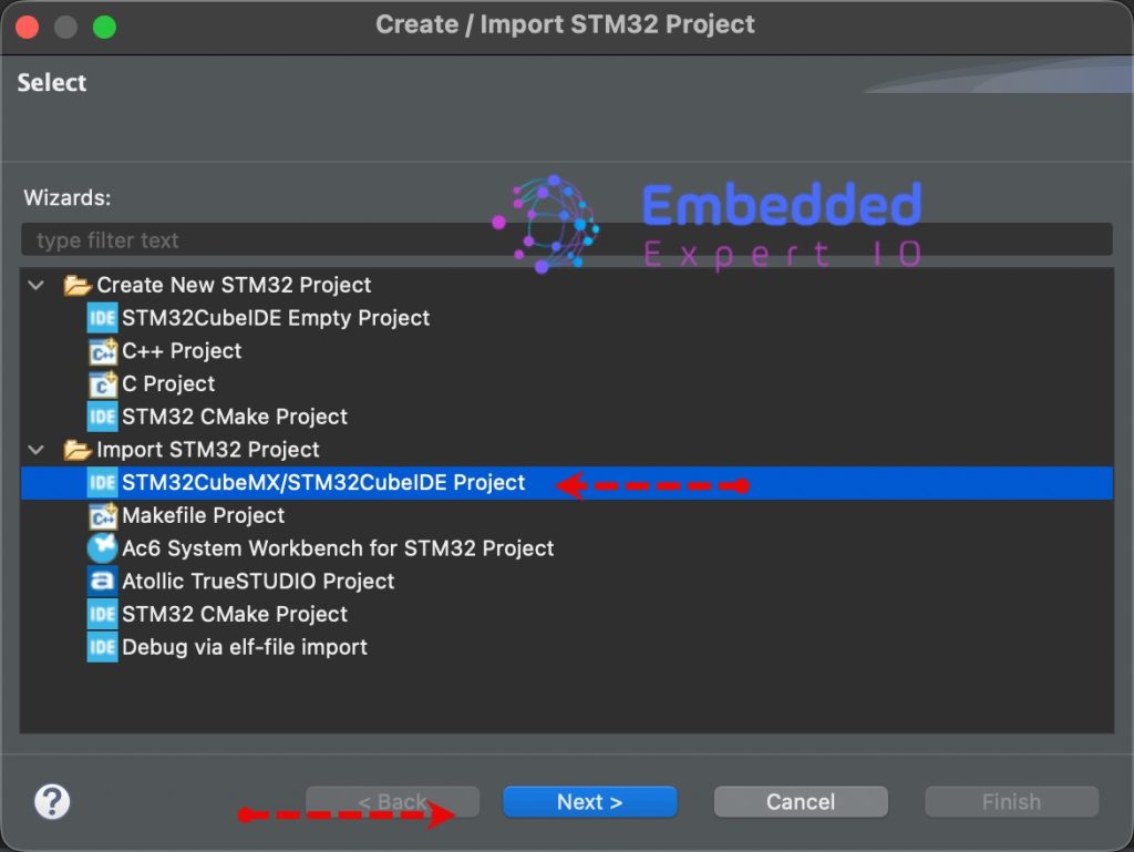
Next, from Import STM32 Project, select STM32CubeMX/STM32CubeIDE Project and click on Next as follows:
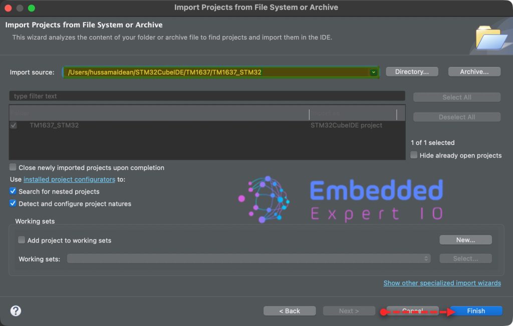
Next, select the folder that contains the .ioc file and click on Finish as follows:
In part 2, we shall see how to develop the firmware and develop the protocol to communicate with the module.
Stay tuned.
Happy coding 😉
Add Comment