
Part 3 of the guide moves beyond basic link verification and introduces practical Modbus RTU transactions in which the master issues read requests to the STM32-based slave. This section focuses on implementing and validating standard read function codes, register addressing, and response formatting so the emulated sensor can return meaningful data in a fully protocol-compliant manner which will be covered next.
In this guide, we shall cover the following:
- Master Request to Read.
- Firmware Development.
- Testing and Results.
1. Master Request to Read:
When the master request to read data, the data frame as following:
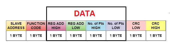
- First byte is the address of the slave.
- Second byte is the function code.
- Third and fourth bytes are the register address high and low byte respectively.
- Fifth and sixth bytes are the number of points high and low byte respectively.
- The fifth and last are the CRC ow and high byte respectively.
This is the typical frame for master request to read from slave.
2. Firmware Development:
First, we shall create header and source file for crc calculation.
Create header and and source file with name of modbus_crc.h and modbus_crc.c respectively as follows:

In modbus_crc.h file, within headerfile guard, declare the following function:
uint16_t crc16(uint8_t *buffer, uint16_t buffer_length);
This function shall calculate the CRC value on the fly.
Hence, the entire header file as follows:
#ifndef INC_MODBUS_CRC_H_
#define INC_MODBUS_CRC_H_

uint16_t crc16(uint8_t *buffer, uint16_t buffer_length);

#endif /* INC_MODBUS_CRC_H_ */
Next, in modbus_crc, include the following header files:
#include "stdint.h"
#include "modbus_crc.h"
Declare the following crc high table:
static const uint8_t table_crc_hi[] = {
    0x00, 0xC1, 0x81, 0x40, 0x01, 0xC0, 0x80, 0x41, 0x01, 0xC0,
    0x80, 0x41, 0x00, 0xC1, 0x81, 0x40, 0x01, 0xC0, 0x80, 0x41,
    0x00, 0xC1, 0x81, 0x40, 0x00, 0xC1, 0x81, 0x40, 0x01, 0xC0,
    0x80, 0x41, 0x01, 0xC0, 0x80, 0x41, 0x00, 0xC1, 0x81, 0x40,
    0x00, 0xC1, 0x81, 0x40, 0x01, 0xC0, 0x80, 0x41, 0x00, 0xC1,
    0x81, 0x40, 0x01, 0xC0, 0x80, 0x41, 0x01, 0xC0, 0x80, 0x41,
    0x00, 0xC1, 0x81, 0x40, 0x01, 0xC0, 0x80, 0x41, 0x00, 0xC1,
    0x81, 0x40, 0x00, 0xC1, 0x81, 0x40, 0x01, 0xC0, 0x80, 0x41,
    0x00, 0xC1, 0x81, 0x40, 0x01, 0xC0, 0x80, 0x41, 0x01, 0xC0,
    0x80, 0x41, 0x00, 0xC1, 0x81, 0x40, 0x00, 0xC1, 0x81, 0x40,
    0x01, 0xC0, 0x80, 0x41, 0x01, 0xC0, 0x80, 0x41, 0x00, 0xC1,
    0x81, 0x40, 0x01, 0xC0, 0x80, 0x41, 0x00, 0xC1, 0x81, 0x40,
    0x00, 0xC1, 0x81, 0x40, 0x01, 0xC0, 0x80, 0x41, 0x01, 0xC0,
    0x80, 0x41, 0x00, 0xC1, 0x81, 0x40, 0x00, 0xC1, 0x81, 0x40,
    0x01, 0xC0, 0x80, 0x41, 0x00, 0xC1, 0x81, 0x40, 0x01, 0xC0,
    0x80, 0x41, 0x01, 0xC0, 0x80, 0x41, 0x00, 0xC1, 0x81, 0x40,
    0x00, 0xC1, 0x81, 0x40, 0x01, 0xC0, 0x80, 0x41, 0x01, 0xC0,
    0x80, 0x41, 0x00, 0xC1, 0x81, 0x40, 0x01, 0xC0, 0x80, 0x41,
    0x00, 0xC1, 0x81, 0x40, 0x00, 0xC1, 0x81, 0x40, 0x01, 0xC0,
    0x80, 0x41, 0x00, 0xC1, 0x81, 0x40, 0x01, 0xC0, 0x80, 0x41,
    0x01, 0xC0, 0x80, 0x41, 0x00, 0xC1, 0x81, 0x40, 0x01, 0xC0,
    0x80, 0x41, 0x00, 0xC1, 0x81, 0x40, 0x00, 0xC1, 0x81, 0x40,
    0x01, 0xC0, 0x80, 0x41, 0x01, 0xC0, 0x80, 0x41, 0x00, 0xC1,
    0x81, 0x40, 0x00, 0xC1, 0x81, 0x40, 0x01, 0xC0, 0x80, 0x41,
    0x00, 0xC1, 0x81, 0x40, 0x01, 0xC0, 0x80, 0x41, 0x01, 0xC0,
    0x80, 0x41, 0x00, 0xC1, 0x81, 0x40
};
For the low:
static const uint8_t table_crc_lo[] = {
    0x00, 0xC0, 0xC1, 0x01, 0xC3, 0x03, 0x02, 0xC2, 0xC6, 0x06,
    0x07, 0xC7, 0x05, 0xC5, 0xC4, 0x04, 0xCC, 0x0C, 0x0D, 0xCD,
    0x0F, 0xCF, 0xCE, 0x0E, 0x0A, 0xCA, 0xCB, 0x0B, 0xC9, 0x09,
    0x08, 0xC8, 0xD8, 0x18, 0x19, 0xD9, 0x1B, 0xDB, 0xDA, 0x1A,
    0x1E, 0xDE, 0xDF, 0x1F, 0xDD, 0x1D, 0x1C, 0xDC, 0x14, 0xD4,
    0xD5, 0x15, 0xD7, 0x17, 0x16, 0xD6, 0xD2, 0x12, 0x13, 0xD3,
    0x11, 0xD1, 0xD0, 0x10, 0xF0, 0x30, 0x31, 0xF1, 0x33, 0xF3,
    0xF2, 0x32, 0x36, 0xF6, 0xF7, 0x37, 0xF5, 0x35, 0x34, 0xF4,
    0x3C, 0xFC, 0xFD, 0x3D, 0xFF, 0x3F, 0x3E, 0xFE, 0xFA, 0x3A,
    0x3B, 0xFB, 0x39, 0xF9, 0xF8, 0x38, 0x28, 0xE8, 0xE9, 0x29,
    0xEB, 0x2B, 0x2A, 0xEA, 0xEE, 0x2E, 0x2F, 0xEF, 0x2D, 0xED,
    0xEC, 0x2C, 0xE4, 0x24, 0x25, 0xE5, 0x27, 0xE7, 0xE6, 0x26,
    0x22, 0xE2, 0xE3, 0x23, 0xE1, 0x21, 0x20, 0xE0, 0xA0, 0x60,
    0x61, 0xA1, 0x63, 0xA3, 0xA2, 0x62, 0x66, 0xA6, 0xA7, 0x67,
    0xA5, 0x65, 0x64, 0xA4, 0x6C, 0xAC, 0xAD, 0x6D, 0xAF, 0x6F,
    0x6E, 0xAE, 0xAA, 0x6A, 0x6B, 0xAB, 0x69, 0xA9, 0xA8, 0x68,
    0x78, 0xB8, 0xB9, 0x79, 0xBB, 0x7B, 0x7A, 0xBA, 0xBE, 0x7E,
    0x7F, 0xBF, 0x7D, 0xBD, 0xBC, 0x7C, 0xB4, 0x74, 0x75, 0xB5,
    0x77, 0xB7, 0xB6, 0x76, 0x72, 0xB2, 0xB3, 0x73, 0xB1, 0x71,
    0x70, 0xB0, 0x50, 0x90, 0x91, 0x51, 0x93, 0x53, 0x52, 0x92,
    0x96, 0x56, 0x57, 0x97, 0x55, 0x95, 0x94, 0x54, 0x9C, 0x5C,
    0x5D, 0x9D, 0x5F, 0x9F, 0x9E, 0x5E, 0x5A, 0x9A, 0x9B, 0x5B,
    0x99, 0x59, 0x58, 0x98, 0x88, 0x48, 0x49, 0x89, 0x4B, 0x8B,
    0x8A, 0x4A, 0x4E, 0x8E, 0x8F, 0x4F, 0x8D, 0x4D, 0x4C, 0x8C,
    0x44, 0x84, 0x85, 0x45, 0x87, 0x47, 0x46, 0x86, 0x82, 0x42,
    0x43, 0x83, 0x41, 0x81, 0x80, 0x40
};
Next, the function shall calculate the crc value as follows:
uint16_t crc16(uint8_t *buffer, uint16_t buffer_length)
{
    uint8_t crc_hi = 0xFF; /* high CRC byte initialized */
    uint8_t crc_lo = 0xFF; /* low CRC byte initialized */
    unsigned int i; /* will index into CRC lookup */

    /* pass through message buffer */
    while (buffer_length--) {
        i = crc_lo ^ *buffer++; /* calculate the CRC  */
        crc_lo = crc_hi ^ table_crc_hi[i];
        crc_hi = table_crc_lo[i];
    }

    return (crc_hi << 8 | crc_lo);
}
This function computes a 16-bit Modbus CRC (CRC-16/IBM) over a byte buffer, which is mandatory for Modbus RTU frames to detect transmission errors.
Here is what each part does:
Function Purpose
uint16_t crc16(uint8_t *buffer, uint16_t buffer_length)
Takes:
buffer→ pointer to the data bytesbuffer_length→ number of bytes to process
Returns:
- The final 16-bit CRC value appended to Modbus frames.
CRC Initialization
uint8_t crc_hi = 0xFF;
uint8_t crc_lo = 0xFF;
Modbus RTU specifies that the CRC register starts at 0xFFFF, so both high and low bytes are initialized to 0xFF.
Processing Each Byte
while (buffer_length--) {
Iterates through every byte in the message.
Index Calculation
i = crc_lo ^ *buffer++;
The incoming data byte is XORed with the current low CRC byte.
The result forms an index into the lookup tables.
This avoids doing slow bit-by-bit polynomial calculations.
Lookup Table Update
crc_lo = crc_hi ^ table_crc_hi[i];
crc_hi = table_crc_lo[i];
Two precomputed tables are used:
table_crc_hi[]table_crc_lo[]
They contain the pre-calculated CRC effects for all 256 possible byte values.
The new CRC:
crc_lobecomes the old high byte XORed with a lookup value.crc_hibecomes the corresponding lookup value.
This updates the CRC register for the processed byte.
Final Return Value
return (crc_hi << 8 | crc_lo);
Combines the two bytes into a 16-bit result:
CRC = (high_byte << 8) | low_byte
Summary
This is a table-driven Modbus CRC-16 implementation that:
✔ Starts with 0xFFFF
✔ Processes each byte using XOR + lookup tables
✔ Produces the standard Modbus CRC
✔ Runs much faster than bitwise CRC algorithm.
Next, create new header and source file with name of modbus.h and modbus.h respectively as follows:

In the header file, we start by including the following header files:
#include "main.h"

#include "stdint.h"
Next, declare a data structure to hold the following:
- Slave address.
- Function code.
- Register address.
- Number of points.
typedef struct
{
	uint8_t Slave_Address;
	uint8_t Function_Code;
	uint16_t Register_Address;
	uint16_t Number_of_Data;

}modbusTypedefStruct;
Next, the function that send the master request to read frame as follows:
void Modbus_ReadRequest(modbusTypedefStruct * ModbusFrame);
Hence, the entire header file as follows:
#ifndef INC_MODBUS_H_
#define INC_MODBUS_H_

#include "main.h"

#include "stdint.h"

typedef struct
{
	uint8_t Slave_Address;
	uint8_t Function_Code;
	uint16_t Register_Address;
	uint16_t Number_of_Data;

}modbusTypedefStruct;

void Modbus_ReadRequest(modbusTypedefStruct * ModbusFrame);


#endif /* INC_MODBUS_H_ */
Next, in modbus.c file, we start by including the following:
#include <modbus.h>

#include "modbus_crc.h"
Next, declare the serial instant that shall be used, USART1 in this case:
extern UART_HandleTypeDef huart1;
Note: It needed to be defined as external since it has been declared in the main.c file.
Next, the function that will send the frame as follows:
void Modbus_ReadRequest(modbusTypedefStruct * ModbusFrame)
{
	uint8_t address	=	ModbusFrame->Slave_Address;

	uint8_t FunCode	=	ModbusFrame->Function_Code;

	uint16_t regAdd= 	ModbusFrame->Register_Address;

	uint16_t numData=	ModbusFrame->Number_of_Data;

	uint8_t buffer[8];


	buffer[0]=address;

	buffer[1]=FunCode;

	buffer[2]=(regAdd>>8)&0xFF;

	buffer[3]=(regAdd)&0xFF;

	buffer[4]= (numData>>8)&0xFF;

	buffer[5]= (numData)&0xFF;

	uint16_t tmp_crc=crc16(buffer,6);

	buffer[6]=tmp_crc&0xFF;
	buffer[7]=(tmp_crc>>8)&0xFF;

	HAL_GPIO_WritePin(GPIOA, GPIO_PIN_0, GPIO_PIN_SET);

	HAL_UART_Transmit(&huart1, buffer, 8, 100);

	HAL_GPIO_WritePin(GPIOA, GPIO_PIN_0, GPIO_PIN_RESET);
}
This function builds and transmits a Modbus RTU read request frame from a master to a slave over UART using RS-485.
It extracts the slave address, function code, register address, and number of registers from the ModbusFrame structure, then places them into an 8-byte buffer following the Modbus RTU format. A CRC-16 is calculated over the first six bytes and appended in low-byte-first order, as required by Modbus. Before transmission, GPIOA pin 0 is set high to enable the RS-485 driver (transmit mode), the frame is sent using HAL_UART_Transmit, and the pin is cleared afterward to return the transceiver to receive mode.
Hence, the source file as follows:
#include <modbus.h>

#include "modbus_crc.h"

extern UART_HandleTypeDef huart1;


void Modbus_ReadRequest(modbusTypedefStruct * ModbusFrame)
{
	uint8_t address	=	ModbusFrame->Slave_Address;

	uint8_t FunCode	=	ModbusFrame->Function_Code;

	uint16_t regAdd= 	ModbusFrame->Register_Address;

	uint16_t numData=	ModbusFrame->Number_of_Data;

	uint8_t buffer[8];


	buffer[0]=address;

	buffer[1]=FunCode;

	buffer[2]=(regAdd>>8)&0xFF;

	buffer[3]=(regAdd)&0xFF;

	buffer[4]= (numData>>8)&0xFF;

	buffer[5]= (numData)&0xFF;

	uint16_t tmp_crc=crc16(buffer,6);

	buffer[6]=tmp_crc&0xFF;
	buffer[7]=(tmp_crc>>8)&0xFF;

	HAL_GPIO_WritePin(GPIOA, GPIO_PIN_0, GPIO_PIN_SET);

	HAL_UART_Transmit(&huart1, buffer, 8, 100);

	HAL_GPIO_WritePin(GPIOA, GPIO_PIN_0, GPIO_PIN_RESET);
}
Thats all for the firmware.
3. Testing and Results:
In main.c, we shall start by including the following header file:
#include "modbus.h"
Next, declare the data structure as follows:
modbusTypedefStruct DataFrame;
Next, in user code begin 2 in main function, populate the data structure with values, the following is for example. Later, a proper values shall be used.
DataFrame.Slave_Address=0x11;
DataFrame.Function_Code=0x03;
DataFrame.Register_Address=0x01;
DataFrame.Number_of_Data=0x02;
In while 1 loop, in user code begin 3, transmit the data each 100ms as follows:
Modbus_ReadRequest(&DataFrame);

HAL_Delay(100);
Save, build and run the project as follows:

By probing the AB pins of the RS485, you should get the following:
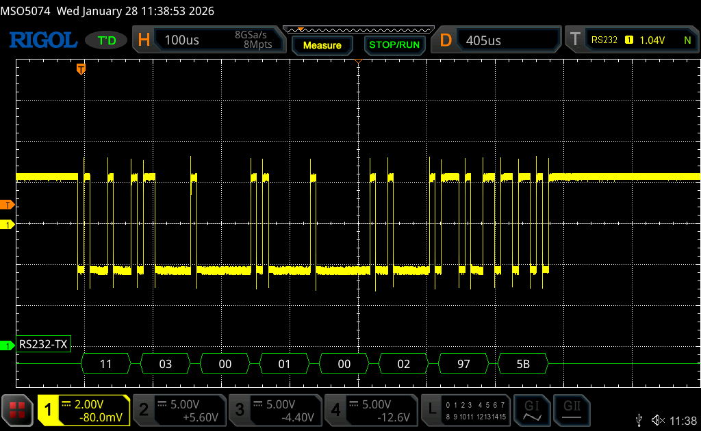
Note: Values are in hex.
Next, we shall develop the firmware to response to request to read by following one of the sensor documentation.
Stay tuned.
Happy coding 😉
Add Comment