This guide introduces the 1.28″ Round LCD Display Module featuring the embedded GC9A01 driver and SPI interface, highlighting its key features, electrical and mechanical specifications, and overall capabilities. Part 1 focuses on configuring STM32CubeMX and STM32CubeIDE to establish reliable communication with the display and prepare the development environment for application-level integration.
In this guide, we shall cover the following:
- Introduction.
- Hardware connection.
- STM32CubeMX setup.
- Importing project to STM32CubeIDE.
1. Introduction:
This application guide provides a comprehensive technical introduction to the 1.28″ Round LCD Display Module featuring the embedded GC9A01 display controller and SPI communication interface, a highly integrated and widely adopted solution for circular TFT panels used in modern embedded products. The GC9A01 is specifically optimized for 240 × 240-pixel round displays, making it particularly well suited for space-constrained and visually driven applications such as smart watches, wearable devices, portable instruments, industrial indicators, medical monitors, home-automation interfaces, control knobs, IoT dashboards, and consumer electronics that demand a distinctive circular user interface. By integrating the complete display-driving engine, internal GRAM frame memory, timing generation logic, and power-control circuitry, the GC9A01 allows a microcontroller to operate a full-color TFT panel with minimal external components and modest firmware complexity.
One of the key strengths of the GC9A01 lies in its rich and mature feature set. The controller supports 16-bit and 18-bit RGB color formats, high-speed SPI operation, and a flexible command architecture that enables fine-grained control over nearly every aspect of the display pipeline. With an internal frame buffer capable of storing the entire screen image, the GC9A01 significantly reduces RAM pressure on the host MCU—an important consideration when working with mid-range STM32 devices. In addition, the controller handles low-level tasks such as screen refresh, partial-window updates, tearing-effect synchronization, inversion control, scrolling, gamma curve adjustment, sleep and idle modes, and programmable orientation through memory-access control registers. These hardware-accelerated functions allow the firmware to concentrate on higher-level graphics composition rather than raw pixel-driving logistics.
On the panel side, typical 1.28″ round GC9A01-based modules employ high-quality TFT or IPS technology, offering vivid colors, good brightness, and wide viewing angles suitable for both indoor and portable outdoor use. The circular form factor opens the door to unique user-interface designs that are difficult to achieve with traditional rectangular screens, which is why such modules are increasingly found in rotary-control HMIs, instrument clusters, gauge displays, fitness trackers, smart thermostats, battery-powered handheld tools, and compact diagnostic equipment. The combination of a distinctive mechanical profile, strong optical performance, and a widely supported controller makes the GC9A01 platform attractive for rapid prototyping as well as production-ready embedded systems.
Because of the controller’s flexibility, a solid understanding of its communication method and configuration requirements is essential before beginning driver development. Most GC9A01 modules expose a 4-wire SPI interface supplemented by control signals such as Data/Command (DC), Reset (RST), Chip Select (CS), and Backlight Enable (BLK). Depending on board design and MCU capability, SPI clock speeds can reach several tens of megahertz, enabling responsive screen updates even without dedicated graphics accelerators. Correct implementation of the initialization sequence is critical, as GC9A01 registers govern pixel format selection (RGB565 or RGB666), column and row address windows, orientation and mirroring, frame-rate control, porch timings, voltage levels, and power-on sequencing. This guide is structured to demystify those steps by presenting a clear and methodical path from hardware awareness to a fully operational display.
Before writing any display-specific firmware, the STM32 development environment must be configured carefully. For that reason, the latter portion of this first part focuses on creating a clean and scalable project using STM32CubeMX and STM32CubeIDE. We will cover selecting and configuring the appropriate SPI peripheral, assigning GPIO pins for all control and backlight signals, tuning the system clock tree to avoid throughput limitations, and generating a project structure that supports later expansion. Recommended SPI parameters, DMA usage for high-speed pixel transfers, HAL versus LL driver considerations, and organizational practices for display-driver source files will also be discussed to ensure long-term maintainability.
By the end of Part 1, readers will possess a thorough understanding of the GC9A01 controller’s architecture and capabilities, recognize where this circular display module fits into real-world products, and have a fully prepared STM32CubeMX project ready for hands-on development. Subsequent sections of the guide will build on this foundation by implementing the low-level communication layer, crafting the initialization command sequence, and developing the first graphics routines to bring the round LCD to life.
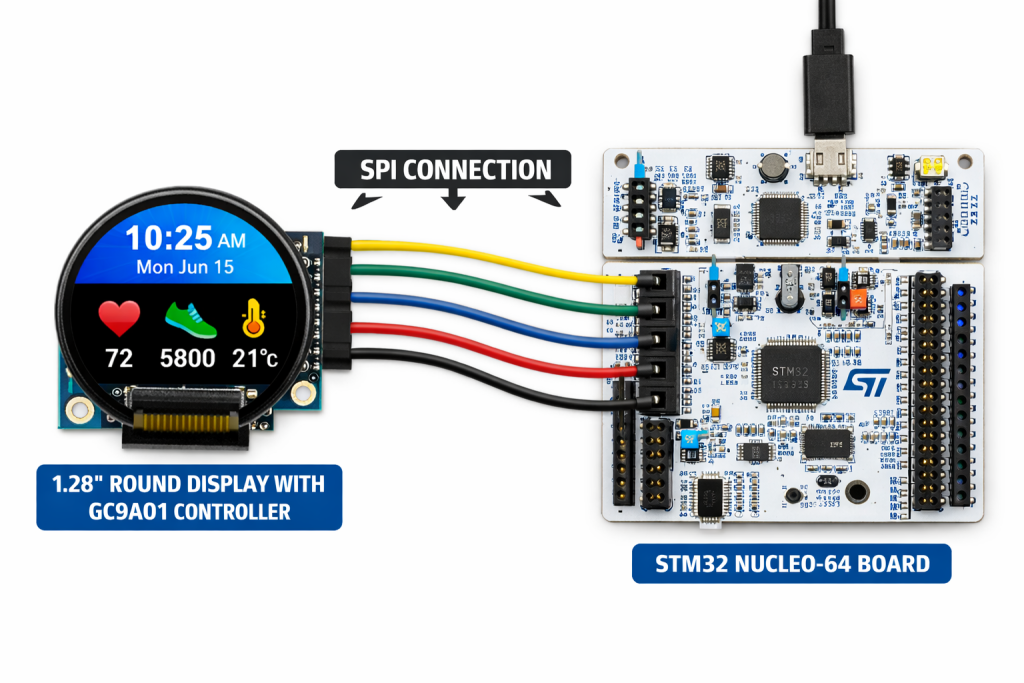
2. Hardware Connection:
The connection as follows:
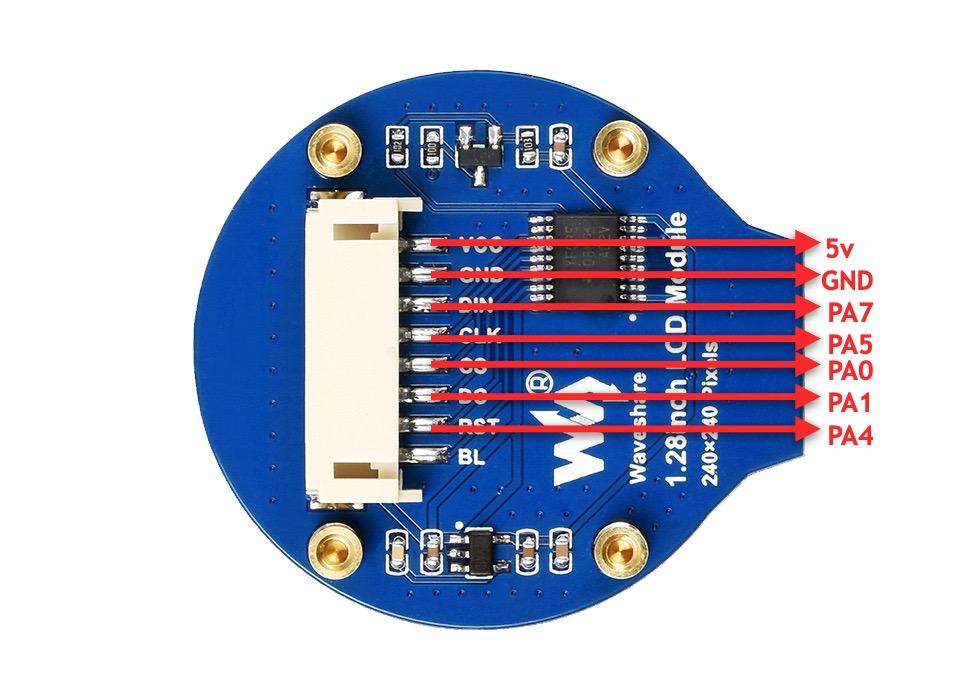
| 1.69inch LCD Module | STM32F411 Nucleo-64 |
| Vcc | 5V |
| GND | GND |
| DIN | PA7 (D11 of Arduino) |
| CLK | PA5 (D13 of Arduino) |
| CS | PA0 (A0 of Arduino) |
| DC | PA1 (A1 of Arduino) |
| RST | PA4 (A2 of Arduino) |
Note: BL is optional, you can leave it floating or connect PWM signal to control the brightness.
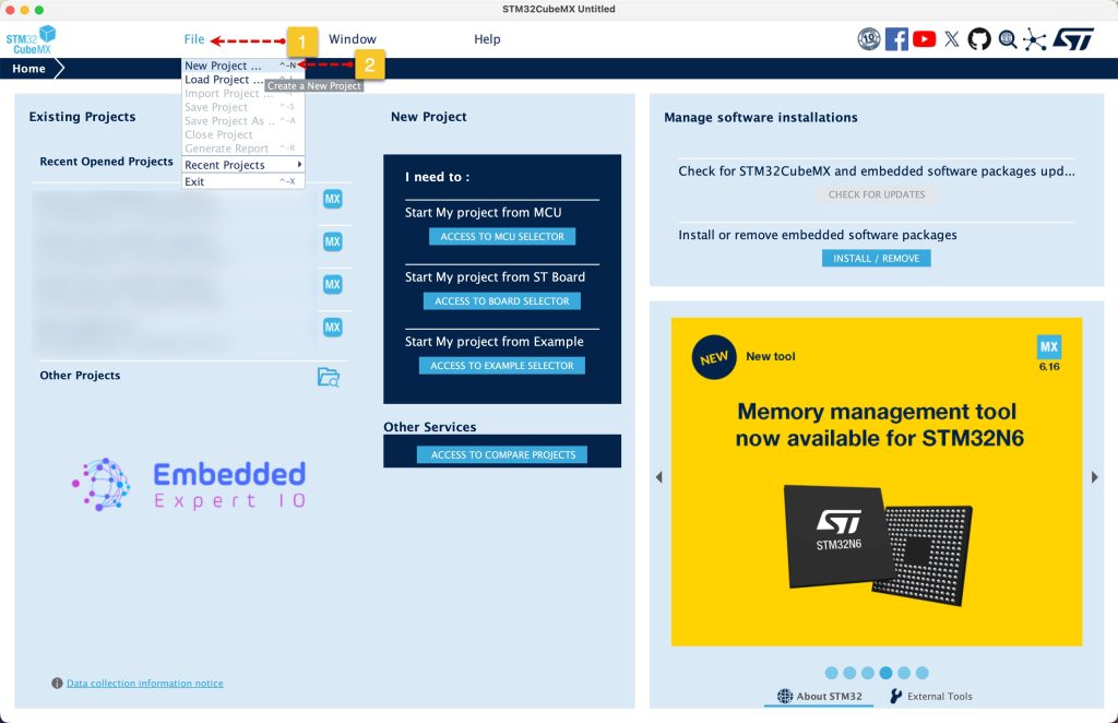
3. STM32CubeMX Setup:
Open STM32CubeMX as start a new project as follows:
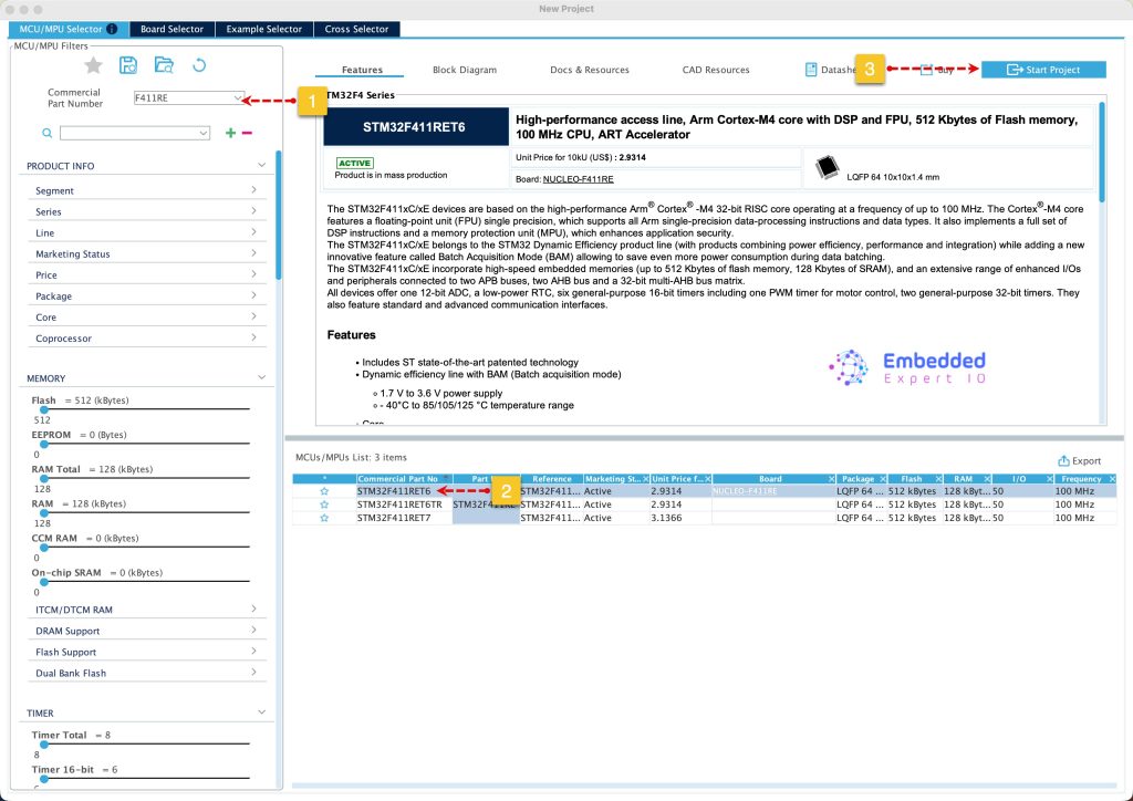
Search for your STM32 MCU, select the MCU and click on Start New Project as follows:
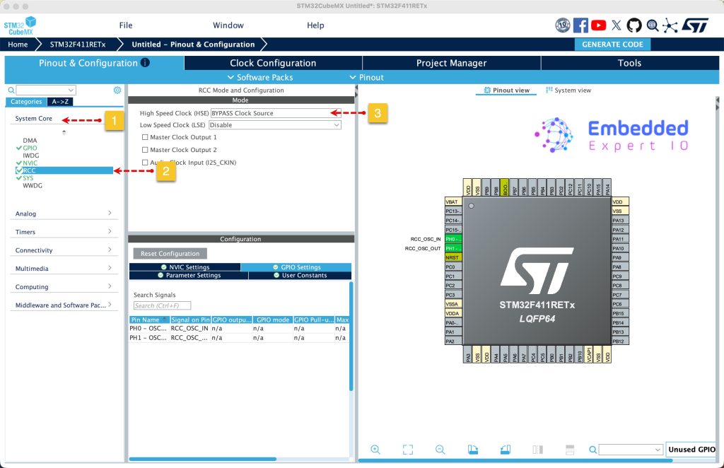
Next, from system core, select RCC and select either Crystal / Ceramic oscillator in case your board has external oscillator or bypass the oscillator in case of Nucleo board. Since this guide uses STM32F411 Nucleo-64, bypass oscillator will be used as follows:
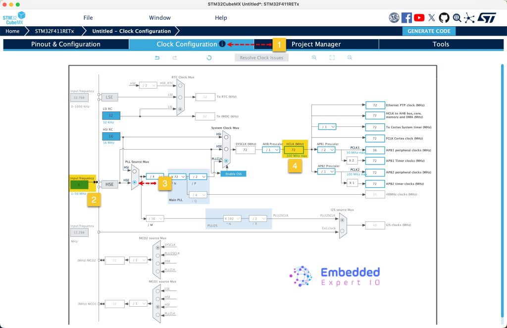
Next, from Clock configuration, set the input frequency to 8MHz, PLL source to HSE and set HCLK frequency to 72MHz. Press enter to set the correct parameters.
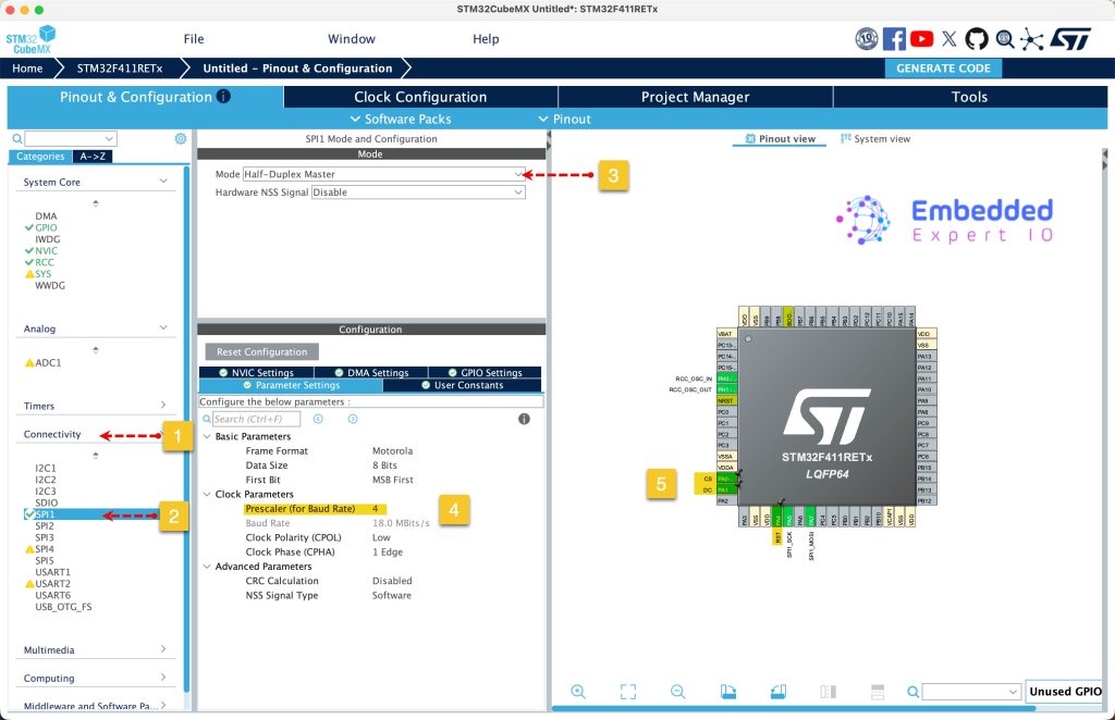
Next, from connectivity, select SPI and set it to master half duplex, set the prescaler to 4. By selecting this, the SPI clock will be 18MHz, good enough given the setup.
Also, set PA0, PA1 and PA4 as output and give then name of CS, DC and RST respectively.
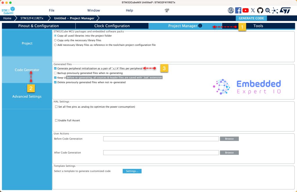
Next, from project manager, select code generation and set generation the peripherals initialization as pair of .c/.h files as follows:
Next, from Project, give the project a name, select the location of the project, select toolchain/IDE to STM32CubeIDE and click on Generate Code as follows:
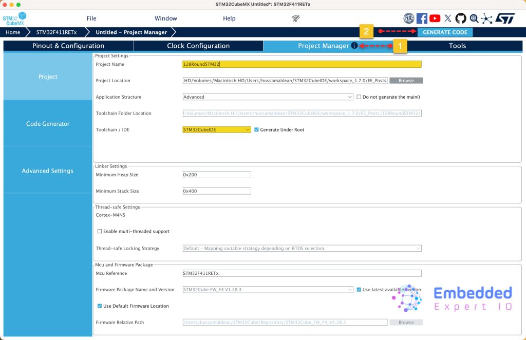
This will generate the project.
4. Importing project to STM32CubeIDE:
Open STM32CubeIDE, select your workspace and click on Launch.
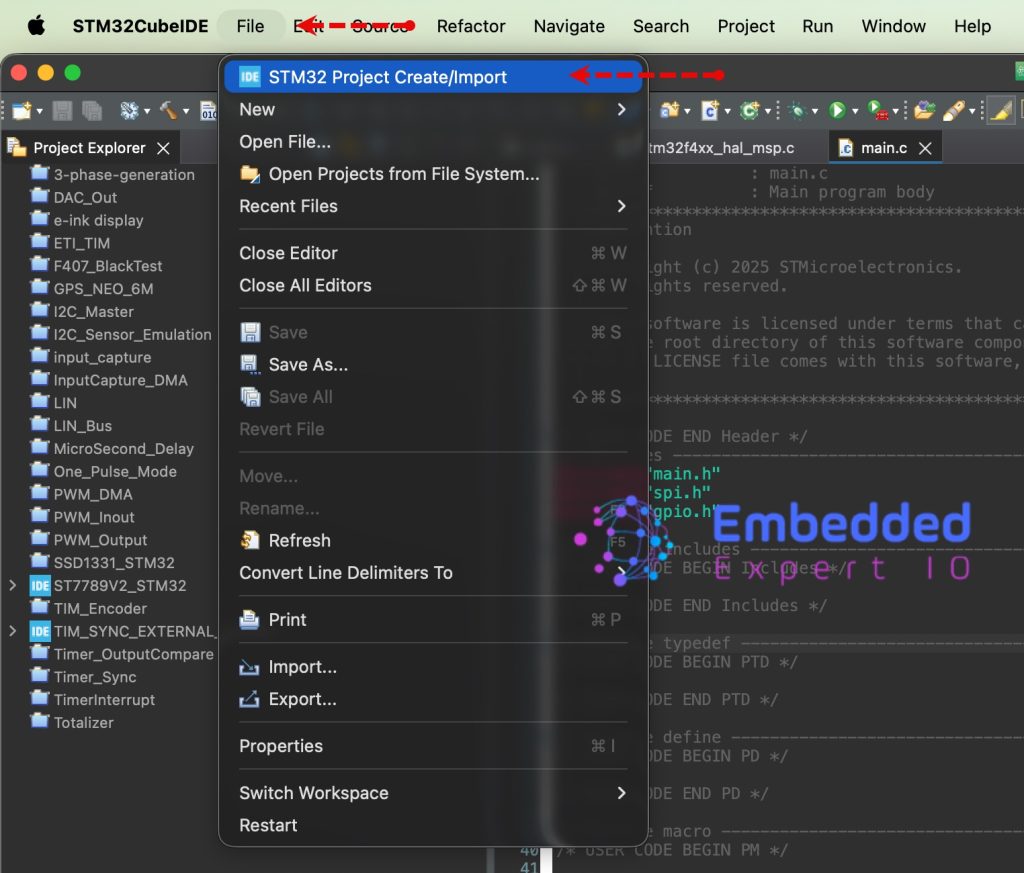
From the IDE, click File and select STM32 Project Create/Import as follows:
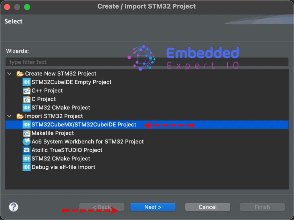
Next, from Import STM32 Project, select STM32CubeMX/STM32CubeIDE Project and click on Next as follows:
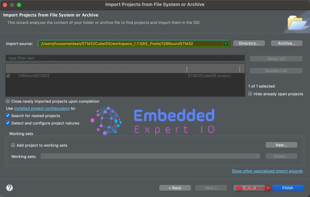
Next, select the folder that contains the .ioc file and click on Finish as follows:
Thats all for part 1.
Stay tuned for part 2 where we shall initialize the LCD and draw random colors to each pixel of the display.
Happy coding 😉
Add Comment