One Pulse Mode (OPM) in STM32 timers allows the generation of a single, precisely timed pulse in response to a trigger event, after which the timer automatically stops. This feature is ideal for applications requiring accurate one-shot signal generation, such as pulse triggering, time-of-flight measurement, ultrasonic bursts, and controlled actuator activation.
In this guide, we shall cover the following:
- Introduction.
- STM32CubeMX configuration.
- Firmware development.
- Connection.
- Results.
1. Introduction:
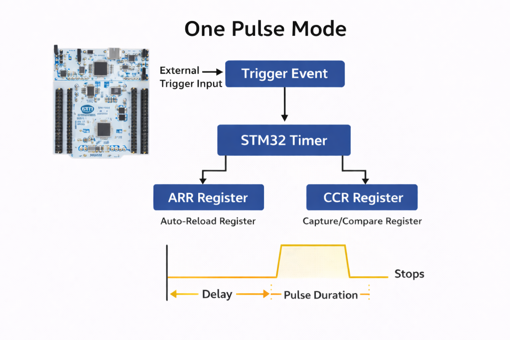
One Pulse Mode (OPM) in STM32 timers is a specialized operating configuration in which the timer generates a single output pulse in response to a defined trigger event and then automatically halts its counter operation. Unlike continuous PWM or periodic output modes, OPM is designed for deterministic, single-shot timing sequences where exactly one pulse—with precisely controlled delay and duration—is required. Once the pulse is completed, the timer disables itself (CEN bit cleared automatically in hardware), ensuring no unintended repetition occurs unless it is explicitly rearmed by software or retriggered via hardware.
At the architectural level, OPM leverages the STM32 timer’s slave mode controller, trigger controller, and output compare units. A trigger source—internal (e.g., another timer’s TRGO) or external (e.g., TIx input pin)—initiates the counter. The timer then progresses from zero (or a preset value) toward the auto-reload register (ARR), while the capture/compare register (CCR) defines the pulse transition timing. This allows independent control of:
- Pulse delay (from trigger event to rising edge)
- Pulse width (duration between active and inactive transitions)
- Polarity (active-high or active-low)
In advanced-control timers such as TIM1 and TIM8 (STM32F4 family), OPM can also operate with complementary outputs, dead-time insertion, and break functionality, making it suitable for power electronics, gate drive control, and safety-critical pulse generation.
One Pulse Mode is particularly important in systems where timing determinism and resource efficiency are critical. It eliminates the need for software-managed delays or polling loops, thereby reducing CPU overhead and jitter. Because the entire pulse sequence is executed in hardware once triggered, timing accuracy is bounded only by the timer clock resolution. This makes OPM highly suitable for:
- Ultrasonic transducer excitation bursts
- Laser or strobe triggering
- Time-of-flight measurements
- Precise actuator control
- ADC sampling synchronization
- Communication framing pulses
From a system design perspective—especially in embedded platforms like STM32F4 where you are already working extensively with timer synchronization and advanced PWM features—OPM becomes a foundational building block for event-driven architectures. It enables clean hardware-based timing chains where one timer event deterministically triggers another, without firmware latency.
In summary, One Pulse Mode transforms the STM32 timer from a periodic waveform generator into a precision event-driven pulse engine. Its hardware-driven execution ensures minimal jitter, high temporal accuracy, and clean synchronization with other peripherals, making it indispensable in advanced embedded control systems.
2. STM32CubeMX Configuration:
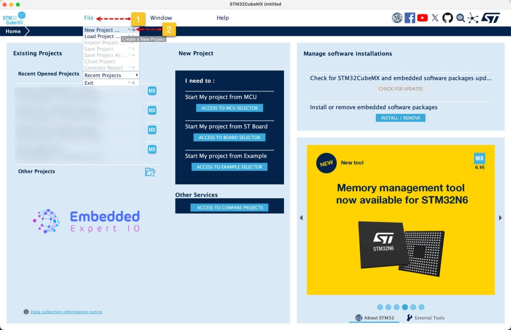
Open STM32CubeMX as start a new project as follows:
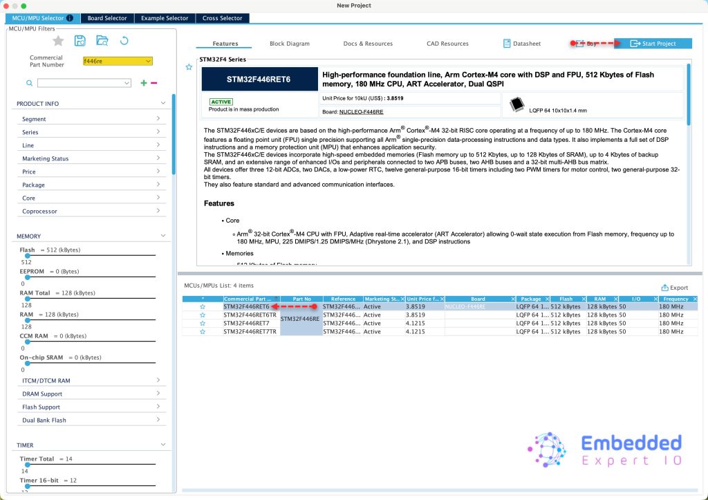
Search for your STM32 MCU, select the MCU and click on Start New Project as follows:
Next, from Timers, select TIM1 and configure it as follows:
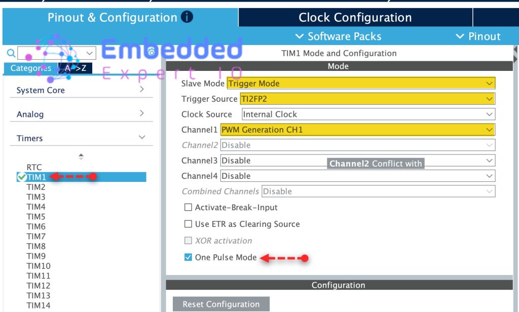
- Set Slave Mode to Trigger Mode.
- Trigger Source TI2FP2, this will set TIM1_CH2 as trigger source.
- Set Channel 1 as PWM generation CH1.
- Enable One Pulse Mode.
Configure the parameters as follows:
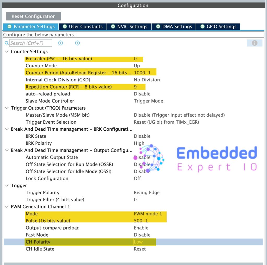
- Prescaller to 0
- Counter period to 1000.
- Repetition counter to 9, this will generate 10 pulses.
For PWM Generation CH1:
- set Mode to PWM mode 1.
- Pulse to 500-1.
- CH Polarity to Low.
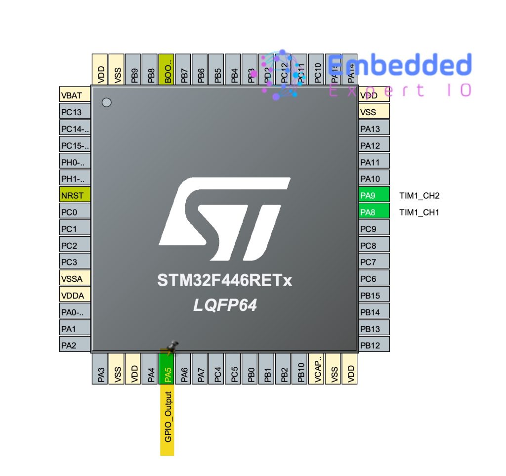
Next, set PA5 as output as follows:
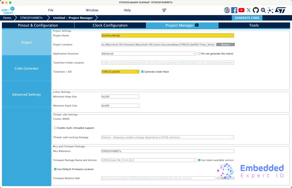
From Project Manager:
Give the project a name, set the location, set toolchain/IDE to STM32CubeIDE and click on Generate Code.
3. Firmware Development
Open STM32CubeIDE, select your workspace and click on Launch.
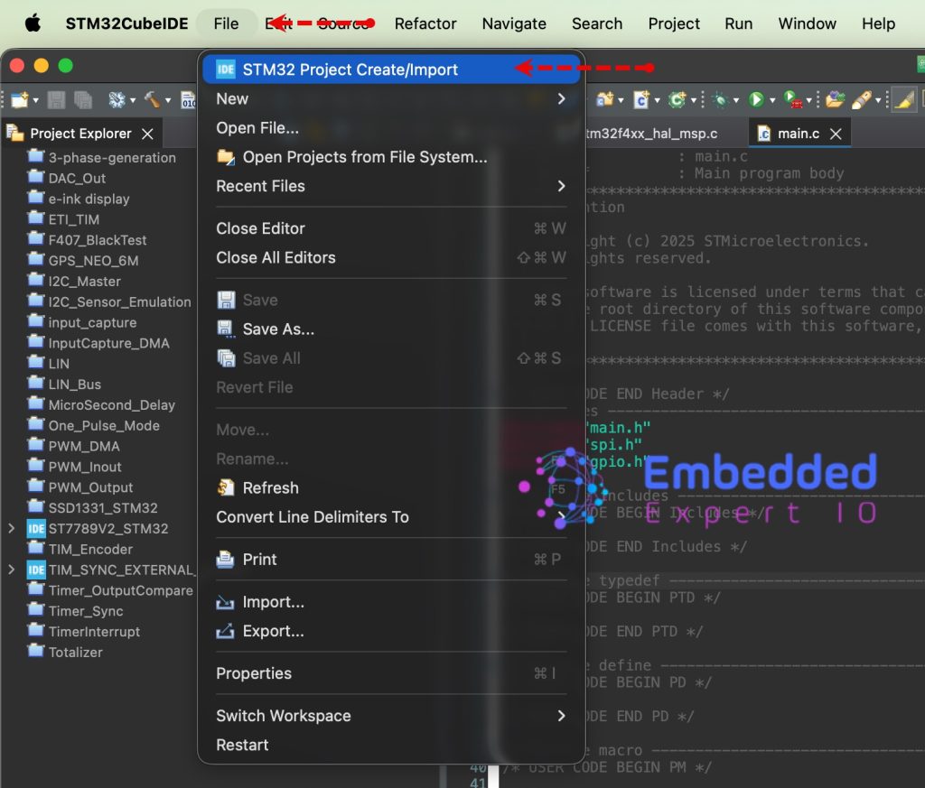
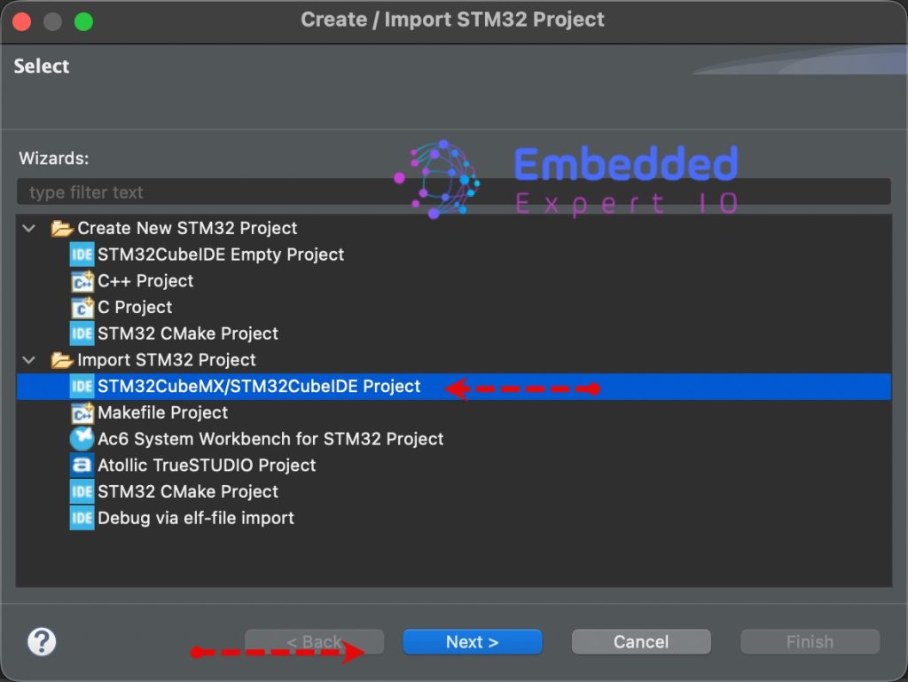
From the IDE, click File and select STM32 Project Create/Import as follows:
Next, from Import STM32 Project, select STM32CubeMX/STM32CubeIDE Project and click on Next as follows:
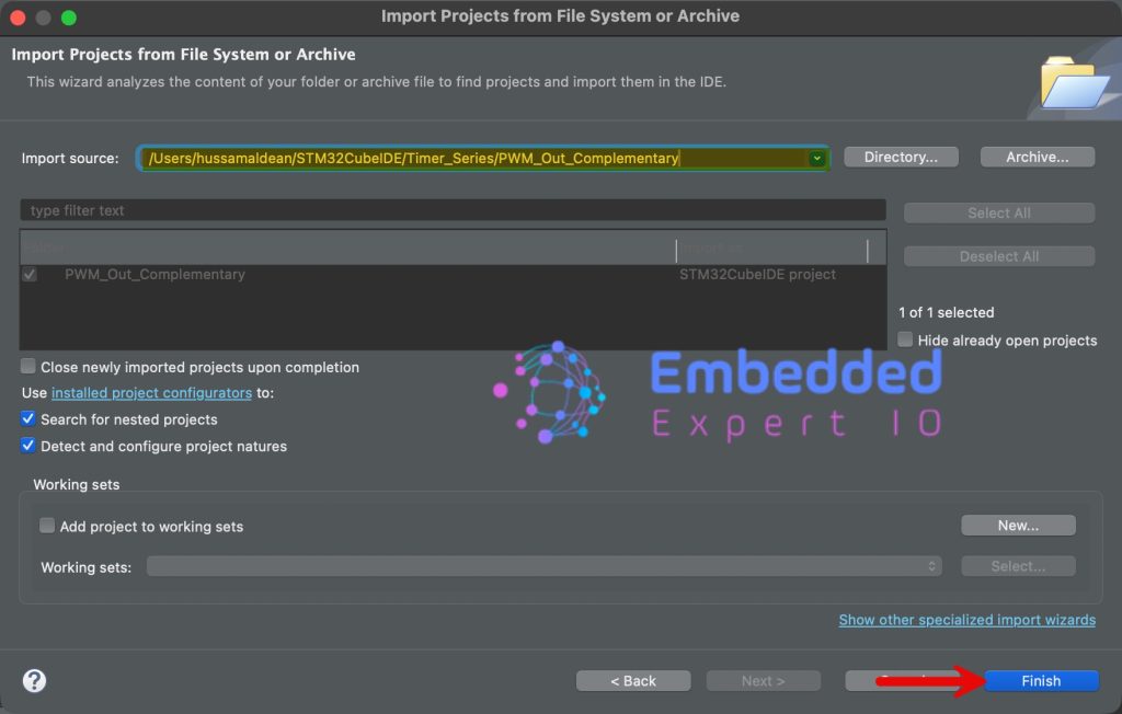
Next, select the folder that contains the .ioc file and click on Finish as follows:
Open main.c file for the project.
In user code begin 2 in main function, start the timer in one pulse mode as follows:
HAL_TIM_OnePulse_Start(&htim1, TIM_CHANNEL_1);
Next, in user code begin 3 in while 1 loop, set PA5 to high and then immediately to Low and wait for 1ms as follows:
HAL_GPIO_WritePin(GPIOA, GPIO_PIN_5, GPIO_PIN_SET);
HAL_GPIO_WritePin(GPIOA, GPIO_PIN_5, GPIO_PIN_RESET);
HAL_Delay(1);
Thats all for the guide, click on run to save the project, build it and flash it as follows:

4. Connection:
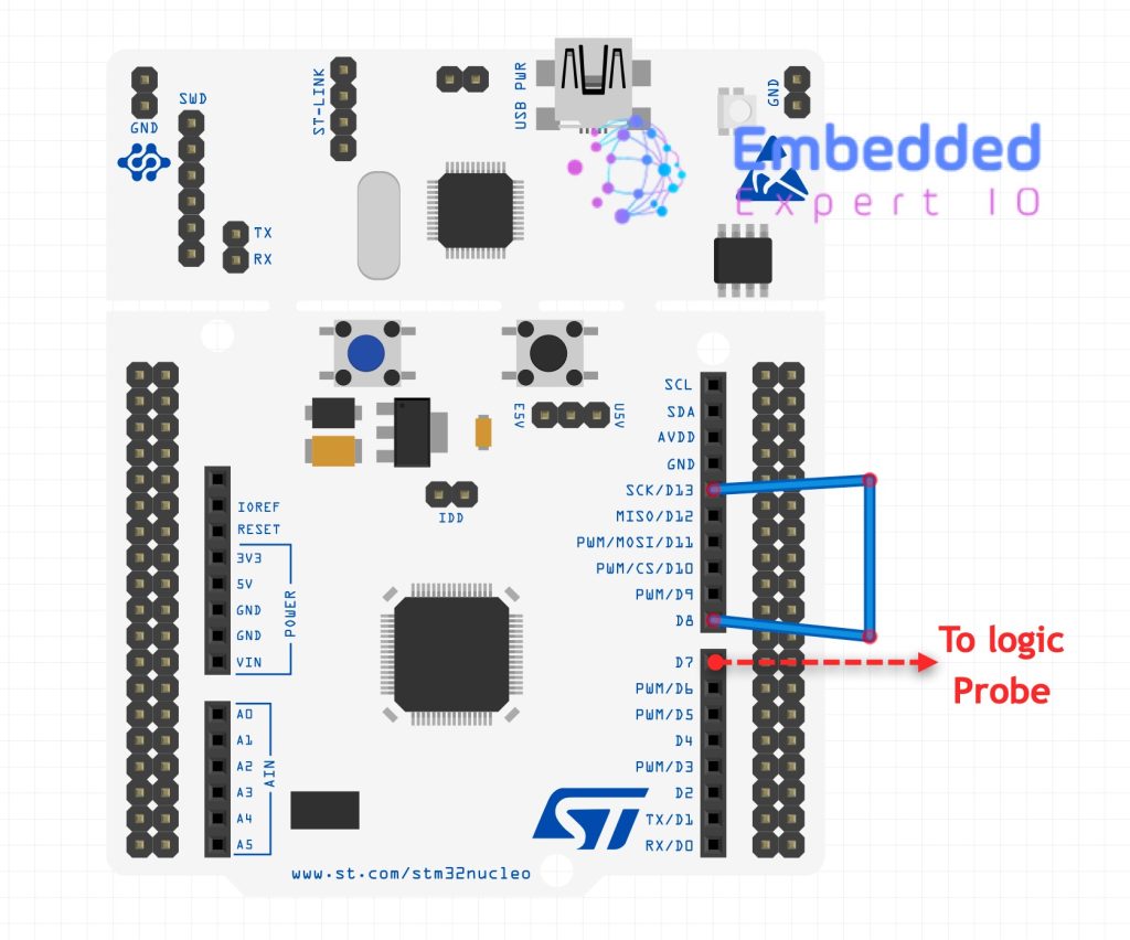
Connect PA9 to PA5 (D8 to D13 of Arduino pins) and connect PA8 (D7 of Arduino pins) to logic probe.
5. Results:
You should get the following:
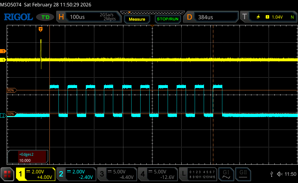
The yellow trace shows PA5, the trigger pin and blue is the PWM output.
The edges are 10 which is expected as we set the repetition to 9.
Feel free to trigger the timer using another timer etc.
Happy coding 😉
Add Comment