Part 2 of this guide focuses on establishing and validating the communication link between a Modbus RTU master and the STM32-based slave using a simple echo mechanism. The master sends a complete Modbus RTU frame and the slave returns the same frame unchanged, allowing verification of UART configuration, RS-485 direction control, and protocol framing before moving to full Modbus register handling.
In this guide, we shall cover the following:
- Importing project to STM32CubeIDE.
- Slave configuration.
- Master configuration.
- Results.
6. Importing Project to STM32CubeIDE:
Open STM32CubeIDE, select your workspace and click on Launch.
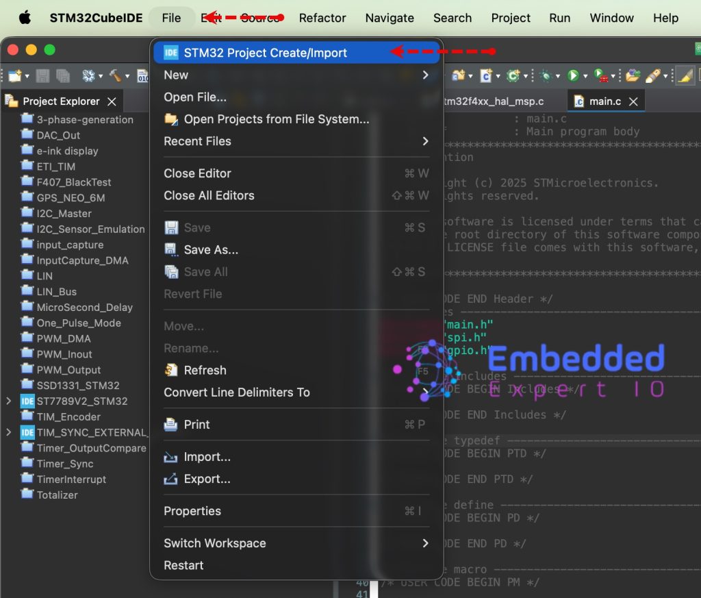
From the IDE, click File and select STM32 Project Create/Import as follows:
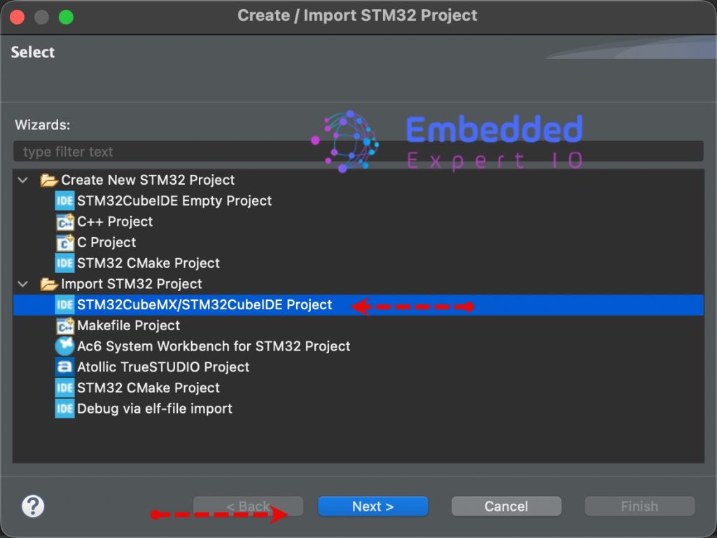
Next, from Import STM32 Project, select STM32CubeMX/STM32CubeIDE Project and click on Next as follows:
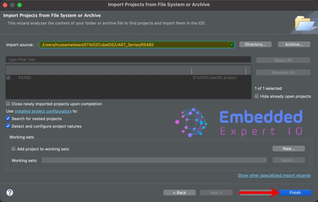
Next, select the folder that contains the .ioc file and click on Finish as follows:
Now, the project is the project window.
Repeat the same step for the other project.
7. Slave Configuration:
Once both projects have been imported, open main.c for the slave project.
In main.c file, in user code begin PV, declare the following:
#define bufferSize 50

uint8_t rs485_buffer[bufferSize];
We are declaring a buffer with size of 50 Byte to hold the received data. The buffer size can vary depending on the requirements. 50 Bytes is more than enough for our application.
Next, in user code begin 0, declare the following function:
void HAL_UARTEx_RxEventCallback(UART_HandleTypeDef *huart, uint16_t Size)

{	if(huart->Instance==USART1)
	{
		HAL_UART_Transmit(huart, rs485_buffer, Size, 100);

		HAL_UARTEx_ReceiveToIdle_IT(&huart1, rs485_buffer, bufferSize);
	}
}
This function will be called either when full 50 characters are received or IDLE line is detected.
Once the function is called, transmit the data that being received and rearm the UART to receive the data in interrupt mode again.
In user code begin 2 in main function, start the UART reception in interrupt mode with IDLE line detection as follows:
HAL_UARTEx_ReceiveToIdle_IT(&huart1, rs485_buffer, bufferSize);
Thats all for the slave configuration.
Save, build and run the project as follows:

8. Master Configuration:
Open main.c file for the master.
In user code being includes, include the following:
#include "stdio.h"
This will provide us access to printf functions.
Next, in user code begin PV, declare the following variable:
uint8_t counter;
The variable will increase with each time the master transmit the data.
#define BufferSize 50

uint8_t TxBuffer[BufferSize];
uint8_t RxBuffer[BufferSize];
- Declare the buffer size (same as the salve which is 5 bytes).
- Tx and Rx buffer to hold the transmitted and received data.
In user code begin 0, declare the following function:
void HAL_UARTEx_RxEventCallback(UART_HandleTypeDef *huart, uint16_t Size)

{	if(huart->Instance==USART1)
	{


		HAL_UARTEx_ReceiveToIdle_IT(&huart1, RxBuffer, BufferSize);
	}
}
Here, we are just rearming the UART to receive the data again.
In user code begin 2 in main function.
In user code begin 2 in main function, start the UART reception in interrupt mode with IDLE line detection as follows:
HAL_UARTEx_ReceiveToIdle_IT(&huart1, RxBuffer, BufferSize);
In while 1 loop:
uint16_t len=sprintf(TxBuffer,"Counter = %d\r\n",++counter);

HAL_GPIO_WritePin(GPIOA, GPIO_PIN_0, GPIO_PIN_SET);

HAL_UART_Transmit(&huart1, TxBuffer, len, 100);

HAL_GPIO_WritePin(GPIOA, GPIO_PIN_0, GPIO_PIN_RESET);

HAL_Delay(100);
Since the master is based on STM32F411 which doesn’t support hardware flow for the RS485, we need to set/reset the DE pin manually. Before starting the transmission, set the DE pin to high, transmit the data and set it back to low.
This way, the master will be able to receive after the transmission has been handled.
Thats all for the master configuration.
Save the project, build it and run it in debugging mode on your STM32F4 board.

9. Results:
Add the TxBuffer and RxBuffer to the live expression and you should get the following:

Next, we shall develop the modbus protocol.
Stay tuned.
Happy coding 😉
Add Comment