
Part 4 focuses on implementing the slave-side response to a Modbus RTU read request issued by the master. In this section, the STM32-based slave processes the received frame, validates the CRC and addressing, and returns a properly formatted response containing the requested register data in full compliance with the Modbus RTU specification.
In this guide, we shall cover the following:
- Slave response to read request.
- Slave Firmware.
- Results.
1. Slave Response to Read Request:
When the slave device receives the read request, it sends the response to the master. The response is shown below
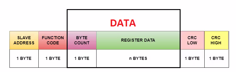
The pattern remains the same with slave address and function code occupying 1 byte each and CRC occupying 2 bytes.
The only change is again in the Data field. It consists of the following:
The actual data itself. The occupancy here depends on how many data bytes the slave is sending.
Byte count (The number of data bytes slave is going to send) occupying 1 Byte
2. Slave Firmware:
First, we shall create header and source file for crc calculation.
Create header and and source file with name of modbus_crc.h and modbus_crc.c respectively as follows:

In modbus_crc.h file, within headerfile guard, declare the following function:
uint16_t crc16(uint8_t *buffer, uint16_t buffer_length);
This function shall calculate the CRC value on the fly.
Hence, the entire header file as follows:
#ifndef INC_MODBUS_CRC_H_
#define INC_MODBUS_CRC_H_

uint16_t crc16(uint8_t *buffer, uint16_t buffer_length);

#endif /* INC_MODBUS_CRC_H_ */
Next, in modbus_crc, include the following header files:
#include "stdint.h"
#include "modbus_crc.h"
Declare the following crc high table:
static const uint8_t table_crc_hi[] = {
    0x00, 0xC1, 0x81, 0x40, 0x01, 0xC0, 0x80, 0x41, 0x01, 0xC0,
    0x80, 0x41, 0x00, 0xC1, 0x81, 0x40, 0x01, 0xC0, 0x80, 0x41,
    0x00, 0xC1, 0x81, 0x40, 0x00, 0xC1, 0x81, 0x40, 0x01, 0xC0,
    0x80, 0x41, 0x01, 0xC0, 0x80, 0x41, 0x00, 0xC1, 0x81, 0x40,
    0x00, 0xC1, 0x81, 0x40, 0x01, 0xC0, 0x80, 0x41, 0x00, 0xC1,
    0x81, 0x40, 0x01, 0xC0, 0x80, 0x41, 0x01, 0xC0, 0x80, 0x41,
    0x00, 0xC1, 0x81, 0x40, 0x01, 0xC0, 0x80, 0x41, 0x00, 0xC1,
    0x81, 0x40, 0x00, 0xC1, 0x81, 0x40, 0x01, 0xC0, 0x80, 0x41,
    0x00, 0xC1, 0x81, 0x40, 0x01, 0xC0, 0x80, 0x41, 0x01, 0xC0,
    0x80, 0x41, 0x00, 0xC1, 0x81, 0x40, 0x00, 0xC1, 0x81, 0x40,
    0x01, 0xC0, 0x80, 0x41, 0x01, 0xC0, 0x80, 0x41, 0x00, 0xC1,
    0x81, 0x40, 0x01, 0xC0, 0x80, 0x41, 0x00, 0xC1, 0x81, 0x40,
    0x00, 0xC1, 0x81, 0x40, 0x01, 0xC0, 0x80, 0x41, 0x01, 0xC0,
    0x80, 0x41, 0x00, 0xC1, 0x81, 0x40, 0x00, 0xC1, 0x81, 0x40,
    0x01, 0xC0, 0x80, 0x41, 0x00, 0xC1, 0x81, 0x40, 0x01, 0xC0,
    0x80, 0x41, 0x01, 0xC0, 0x80, 0x41, 0x00, 0xC1, 0x81, 0x40,
    0x00, 0xC1, 0x81, 0x40, 0x01, 0xC0, 0x80, 0x41, 0x01, 0xC0,
    0x80, 0x41, 0x00, 0xC1, 0x81, 0x40, 0x01, 0xC0, 0x80, 0x41,
    0x00, 0xC1, 0x81, 0x40, 0x00, 0xC1, 0x81, 0x40, 0x01, 0xC0,
    0x80, 0x41, 0x00, 0xC1, 0x81, 0x40, 0x01, 0xC0, 0x80, 0x41,
    0x01, 0xC0, 0x80, 0x41, 0x00, 0xC1, 0x81, 0x40, 0x01, 0xC0,
    0x80, 0x41, 0x00, 0xC1, 0x81, 0x40, 0x00, 0xC1, 0x81, 0x40,
    0x01, 0xC0, 0x80, 0x41, 0x01, 0xC0, 0x80, 0x41, 0x00, 0xC1,
    0x81, 0x40, 0x00, 0xC1, 0x81, 0x40, 0x01, 0xC0, 0x80, 0x41,
    0x00, 0xC1, 0x81, 0x40, 0x01, 0xC0, 0x80, 0x41, 0x01, 0xC0,
    0x80, 0x41, 0x00, 0xC1, 0x81, 0x40
};
For the low:
static const uint8_t table_crc_lo[] = {
    0x00, 0xC0, 0xC1, 0x01, 0xC3, 0x03, 0x02, 0xC2, 0xC6, 0x06,
    0x07, 0xC7, 0x05, 0xC5, 0xC4, 0x04, 0xCC, 0x0C, 0x0D, 0xCD,
    0x0F, 0xCF, 0xCE, 0x0E, 0x0A, 0xCA, 0xCB, 0x0B, 0xC9, 0x09,
    0x08, 0xC8, 0xD8, 0x18, 0x19, 0xD9, 0x1B, 0xDB, 0xDA, 0x1A,
    0x1E, 0xDE, 0xDF, 0x1F, 0xDD, 0x1D, 0x1C, 0xDC, 0x14, 0xD4,
    0xD5, 0x15, 0xD7, 0x17, 0x16, 0xD6, 0xD2, 0x12, 0x13, 0xD3,
    0x11, 0xD1, 0xD0, 0x10, 0xF0, 0x30, 0x31, 0xF1, 0x33, 0xF3,
    0xF2, 0x32, 0x36, 0xF6, 0xF7, 0x37, 0xF5, 0x35, 0x34, 0xF4,
    0x3C, 0xFC, 0xFD, 0x3D, 0xFF, 0x3F, 0x3E, 0xFE, 0xFA, 0x3A,
    0x3B, 0xFB, 0x39, 0xF9, 0xF8, 0x38, 0x28, 0xE8, 0xE9, 0x29,
    0xEB, 0x2B, 0x2A, 0xEA, 0xEE, 0x2E, 0x2F, 0xEF, 0x2D, 0xED,
    0xEC, 0x2C, 0xE4, 0x24, 0x25, 0xE5, 0x27, 0xE7, 0xE6, 0x26,
    0x22, 0xE2, 0xE3, 0x23, 0xE1, 0x21, 0x20, 0xE0, 0xA0, 0x60,
    0x61, 0xA1, 0x63, 0xA3, 0xA2, 0x62, 0x66, 0xA6, 0xA7, 0x67,
    0xA5, 0x65, 0x64, 0xA4, 0x6C, 0xAC, 0xAD, 0x6D, 0xAF, 0x6F,
    0x6E, 0xAE, 0xAA, 0x6A, 0x6B, 0xAB, 0x69, 0xA9, 0xA8, 0x68,
    0x78, 0xB8, 0xB9, 0x79, 0xBB, 0x7B, 0x7A, 0xBA, 0xBE, 0x7E,
    0x7F, 0xBF, 0x7D, 0xBD, 0xBC, 0x7C, 0xB4, 0x74, 0x75, 0xB5,
    0x77, 0xB7, 0xB6, 0x76, 0x72, 0xB2, 0xB3, 0x73, 0xB1, 0x71,
    0x70, 0xB0, 0x50, 0x90, 0x91, 0x51, 0x93, 0x53, 0x52, 0x92,
    0x96, 0x56, 0x57, 0x97, 0x55, 0x95, 0x94, 0x54, 0x9C, 0x5C,
    0x5D, 0x9D, 0x5F, 0x9F, 0x9E, 0x5E, 0x5A, 0x9A, 0x9B, 0x5B,
    0x99, 0x59, 0x58, 0x98, 0x88, 0x48, 0x49, 0x89, 0x4B, 0x8B,
    0x8A, 0x4A, 0x4E, 0x8E, 0x8F, 0x4F, 0x8D, 0x4D, 0x4C, 0x8C,
    0x44, 0x84, 0x85, 0x45, 0x87, 0x47, 0x46, 0x86, 0x82, 0x42,
    0x43, 0x83, 0x41, 0x81, 0x80, 0x40
};
Next, the function shall calculate the crc value as follows:
uint16_t crc16(uint8_t *buffer, uint16_t buffer_length)
{
    uint8_t crc_hi = 0xFF; /* high CRC byte initialized */
    uint8_t crc_lo = 0xFF; /* low CRC byte initialized */
    unsigned int i; /* will index into CRC lookup */

    /* pass through message buffer */
    while (buffer_length--) {
        i = crc_lo ^ *buffer++; /* calculate the CRC  */
        crc_lo = crc_hi ^ table_crc_hi[i];
        crc_hi = table_crc_lo[i];
    }

    return (crc_hi << 8 | crc_lo);
}
This function computes a 16-bit Modbus CRC (CRC-16/IBM) over a byte buffer, which is mandatory for Modbus RTU frames to detect transmission errors.
Here is what each part does:
Function Purpose
uint16_t crc16(uint8_t *buffer, uint16_t buffer_length)
Takes:
buffer→ pointer to the data bytesbuffer_length→ number of bytes to process
Returns:
- The final 16-bit CRC value appended to Modbus frames.
CRC Initialization
uint8_t crc_hi = 0xFF;
uint8_t crc_lo = 0xFF;
Modbus RTU specifies that the CRC register starts at 0xFFFF, so both high and low bytes are initialized to 0xFF.
Processing Each Byte
while (buffer_length--) {
Iterates through every byte in the message.
Index Calculation
i = crc_lo ^ *buffer++;
The incoming data byte is XORed with the current low CRC byte.
The result forms an index into the lookup tables.
This avoids doing slow bit-by-bit polynomial calculations.
Lookup Table Update
crc_lo = crc_hi ^ table_crc_hi[i];
crc_hi = table_crc_lo[i];
Two precomputed tables are used:
table_crc_hi[]table_crc_lo[]
They contain the pre-calculated CRC effects for all 256 possible byte values.
The new CRC:
crc_lobecomes the old high byte XORed with a lookup value.crc_hibecomes the corresponding lookup value.
This updates the CRC register for the processed byte.
Final Return Value
return (crc_hi << 8 | crc_lo);
Combines the two bytes into a 16-bit result:
CRC = (high_byte << 8) | low_byte
Summary
This is a table-driven Modbus CRC-16 implementation that:
✔ Starts with 0xFFFF
✔ Processes each byte using XOR + lookup tables
✔ Produces the standard Modbus CRC
✔ Runs much faster than bitwise CRC algorithm.
Next, create new header and source file with name of modbus.h and modbus.h respectively as follows:

In the header file, we start by including the following header files:
#include "main.h"

#include "stdint.h"
Next, declare a data structure to hold the following:
- Slave address.
- Function code.
- Register address.
- Number of points.
typedef struct
{
	uint8_t Slave_Address;
	uint8_t Function_Code;
	uint16_t Register_Address;
	uint16_t Number_of_Data;

}modbusTypedefStruct;
Next, declare a function that will extract the slave address, function code, register address and number of data as follows:
void modbus_receive(uint8_t *buffer, modbusTypedefStruct * modbus);
Also, declare the function that will send the data when master request to read as follows:
void modbus_slave_transmit(uint8_t Addr, uint8_t func_code,uint8_t count, uint8_t *Data);
Hence, the header file as follows:
#ifndef INC_MODBUS_H_
#define INC_MODBUS_H_

#include "main.h"

#include "stdint.h"

typedef struct
{
	uint8_t Slave_Address;
	uint8_t Function_Code;
	uint16_t Register_Address;
	uint16_t Number_of_Data;

}modbusTypedefStruct;


void modbus_receive(uint8_t *buffer, modbusTypedefStruct * modbus);

void modbus_slave_transmit(uint8_t Addr, uint8_t func_code,uint8_t count, uint8_t *Data);


#endif /* INC_MODBUS_H_ */
Next, in modbus.c source, start by including the following header file:
#include "modbus.h"

#include "modbus_crc.h"
Next, declare the serial instant that shall be used, USART1 in this case:
extern UART_HandleTypeDef huart1;
For the function that extract the slave address, function code, register address and number of data:
void modbus_receive(uint8_t *buffer, modbusTypedefStruct * modbus)
{
	uint16_t temp_crc;
	temp_crc=buffer[6]|(buffer[7]<<8);

	uint16_t temp_crc_cal;

	temp_crc_cal= crc16(&buffer[0],6);

	if(temp_crc==temp_crc_cal)
	{

		modbus->Slave_Address=buffer[0];

		modbus->Function_Code=buffer[1];

		modbus->Register_Address=(buffer[2]<<8)|(buffer[3]);

		modbus->Number_of_Data=(buffer[4]<<8)|(buffer[5]);

	}

	else
	{
		return;
	}

}
This function receives and validates a Modbus RTU request frame, then extracts its core fields into a structured format.
First, it reconstructs the received CRC from buffer[6] and buffer[7] (low byte first, as per Modbus RTU). It then recalculates the CRC over the first six bytes of the frame using crc16() and compares the result with the received CRC. If both match, the frame integrity is confirmed and the function extracts the Slave Address, Function Code, Register Address, and Number of Data (register count) from the buffer and stores them in the modbus structure. If the CRC check fails, the function exits immediately, discarding the corrupted frame.
Next, the function that transmits the requested data as follows:
void modbus_slave_transmit(uint8_t Addr, uint8_t func_code,uint8_t count, uint8_t *Data)
{
	uint8_t tempArray[5+count];

	tempArray[0]=Addr;
	tempArray[1]=func_code;
	tempArray[2]=count;

	for(int i=0;i<count;i++)
	{
		tempArray[3+i]=Data[i];
	}

	uint16_t crc=crc16(tempArray,count+3);

	tempArray[5+count-2]=(crc>>8)&0xFF;
	tempArray[5+count-1]=(crc)&0xFF;

	HAL_UART_Transmit(&huart1, tempArray, 5+count, 500);

}
This function constructs and transmits a Modbus RTU slave response frame over UART.
It first creates a temporary array sized to hold the full response: slave address (1 byte), function code (1 byte), byte count (1 byte), data payload (count bytes), and CRC (2 bytes). The first three bytes are assigned as Addr, func_code, and count, then the loop copies the response data into the frame starting at index 3.
Next, a CRC-16 is calculated over the address, function code, byte count, and data (count + 3 bytes). The resulting CRC is appended to the end of the frame (two bytes), and finally HAL_UART_Transmit() sends the complete 5 + count byte frame to the master.
Hence, the source file as follows:
#include "modbus.h"

#include "modbus_crc.h"

extern UART_HandleTypeDef huart1;

void modbus_receive(uint8_t *buffer, modbusTypedefStruct * modbus)
{
	uint16_t temp_crc;
	temp_crc=buffer[6]|(buffer[7]<<8);

	uint16_t temp_crc_cal;

	temp_crc_cal= crc16(&buffer[0],6);

	if(temp_crc==temp_crc_cal)
	{

		modbus->Slave_Address=buffer[0];

		modbus->Function_Code=buffer[1];

		modbus->Register_Address=(buffer[2]<<8)|(buffer[3]);

		modbus->Number_of_Data=(buffer[4]<<8)|(buffer[5]);

	}

	else
	{
		return;
	}

}

void modbus_slave_transmit(uint8_t Addr, uint8_t func_code,uint8_t count, uint8_t *Data)
{
	uint8_t tempArray[5+count];

	tempArray[0]=Addr;
	tempArray[1]=func_code;
	tempArray[2]=count;

	for(int i=0;i<count;i++)
	{
		tempArray[3+i]=Data[i];
	}

	uint16_t crc=crc16(tempArray,count+3);

	tempArray[5+count-2]=(crc>>8)&0xFF;
	tempArray[5+count-1]=(crc)&0xFF;

	HAL_UART_Transmit(&huart1, tempArray, 5+count, 500);

}
Next, in main.c:
Include the modbus and stlib.h header files as follows:
#include "modbus.h"
#include "stdlib.h"
Next, declare the data structure that holds the read request information:
modbusTypedefStruct modbusFrame;
Declare a volatile flag to let us know when the data has been received as follows:
volatile uint8_t newData;
Modify HAL_UARTEx_RxEventCallback as follows:
void HAL_UARTEx_RxEventCallback(UART_HandleTypeDef *huart, uint16_t Size)

{	if(huart->Instance==USART1)
	{
		modbus_receive(rs485_buffer,&modbusFrame);
		HAL_UARTEx_ReceiveToIdle_IT(&huart1, rs485_buffer, bufferSize);
		newData=1;

	}
}
Next, in user code begin 3 in while 1 loop:
if(newData==1)
{
  if(modbusFrame.Slave_Address==0x11)
  {
    if(modbusFrame.Function_Code==0x03) //Read Request
    {
      uint8_t data[2];
      data[0]=random()%255;
      data[1]=random()%255;
      modbus_slave_transmit(modbusFrame.Slave_Address,modbusFrame.Function_Code,2,data);
      newData=0;
    }
  }

}
Thats all for the firmware.
Save, build and run the project as follows:

3. Results:
By launching a debug session when the master is connected to your PC, you should get the following:
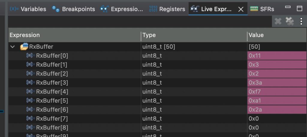
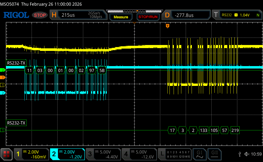
We have successfully send a response to the master.
Next, we shall implement the write request.
Stay tuned.
Happy coding 😉
Add Comment