This guide demonstrates how to emulate a Modbus RTU sensor on an STM32 microcontroller, enabling the device to behave as a compliant Modbus slave over a serial interface such as RS-485 or UART. The objective is to provide a clear, practical reference for implementing register mapping, request handling, and protocol timing in embedded applications where physical sensors are unavailable or need to be simulated for testing and development.
In this guide, we shall cover the following:
- Introduction.
- Modbus RTU.
- Master configuration.
- Slave configuration.
- Hardware connection.
1. Introduction:
Modbus RTU is one of the most established and widely deployed communication protocols in industrial automation, process control, and building management systems. Its longevity is largely due to its simplicity, deterministic behavior, and ability to operate reliably over low-cost serial links such as RS-485 in electrically noisy environments. Despite its age, Modbus RTU remains a fundamental protocol that engineers must understand and support when developing industrial controllers, gateways, data loggers, and supervisory systems. As a result, having a practical and repeatable method to test and validate Modbus-based communication is an essential part of any embedded development workflow.
In real-world projects, firmware development often begins long before the final hardware or field sensors are available, or it must continue in parallel with mechanical, electrical, or system-level integration. In other cases, engineers need a controlled and predictable Modbus slave device to reproduce edge cases, validate timeout handling, or verify master-side logic under known conditions. Emulating a Modbus RTU sensor solves these challenges by allowing a microcontroller to mimic the behavior of an actual sensor, including register maps, data types, response timing, and error handling, without any dependency on external hardware. This approach significantly reduces development risk and accelerates system bring-up and validation.
This guide is dedicated to the implementation of a Modbus RTU sensor emulator using an STM32 microcontroller, a platform well-suited for industrial communication due to its robust UART peripherals, flexible timer architecture, and strong ecosystem of development tools. The guide walks through the conceptual and practical aspects of configuring the STM32 to act as a Modbus RTU slave device, capable of responding correctly to standard Modbus function codes over an RS-485 physical layer. Particular attention is given to protocol framing, CRC calculation, silent interval timing, and direction control of the RS-485 transceiver, all of which are critical for achieving full Modbus RTU compliance.
Beyond basic communication, the guide also addresses how virtual sensor data can be modeled and exposed through Modbus registers in a way that closely resembles real-world devices. This includes structuring holding and input registers, simulating changing measurements, and maintaining consistent behavior across multiple requests. Such an emulation setup is invaluable not only for firmware development and debugging, but also for system-level testing, factory acceptance tests, training, and demonstrations. By the end of this guide, the reader will have a clear and structured reference for building a reliable Modbus RTU sensor emulator on STM32, suitable for use in both development and industrial validation environments.
2. Modbus RTU:
Modbus RTU is an open serial protocol derived from the master/slave architecture (now client/server) originally developed by Modicon (now Schneider Electric). It is a widely accepted serial level protocol due to its ease of use and reliability. Modbus RTU is widely used within Building Management Systems (BMS) and Industrial Automation Systems (IAS).
Modbus RTU messages are a simple 16-bit structure with a Cyclic-Redundant Checksum. The simplicity of these messages ensures reliability. Due to this simplicity, the basic 16-bit Modbus RTU register structure can be used to pack in floating point, tables, ASCII text, queues, and other unrelated data.
This protocol primarily uses an RS-232 or RS-485 serial interfaces for communications and is supported by every commercial SCADA, HMI, OPC server and data acquisition software program in the marketplace. This makes it very easy to integrate Modbus-compatible equipment into new or existing monitoring and control applications.
Modbus Communication

The RTU version uses a client/server technique to communicate between devices. Meaning, any application that utilizes the RTU protocol will have a client and at least one server. A client is typically a host supervisory computer running software that will communicate with one or more server devices.
Modbus enables client/server communication between devices connected through buses or networks. On the OSI Model, Modbus is positioned at Level 7. It is intended to be a request/reply protocol and delivers services specified by function codes. The function codes of the protocol are elements of its request/reply Protocol Data Unit.
In order to build the Modbus application data unit, the client must initiate a Modbus transaction. It is the function that informs the server as to which type of action to perform. The format of a request initiated by a client is established by the application protocol. The function code field is then coded into one byte. Only codes within the range of 1 through 255 are considered valid, with 128-255 being reserved for exception responses. When the client sends a message to the server, it is the function code field that informs the server of what type of action to perform.
To define multiple actions, some functions will have sub-function codes added to them. For instance, the client can read the On/Off states of a group of discreet outputs or inputs. It could also read/write the data contents of a group of registers. When the client receives the server response, the function code field is used by the server to indicate either an error-free response or an exception response. The server echoes to the request of the initial function code in the case of a normal response.
Modbus RTU Data Representation

Like everything else about Modbus, the data representation is simple. In fact, data is represented more simply in Modbus than in any other industrial protocol you’ll ever find. The bit of least importance is sent and received first. All devices within the network must interpret each transmitted byte analogously in this manner.
There are no methods for automated recognition of baud rates. The same baud rate must be utilized by the server(s) and client connected to the bus. No specific baud rate is specified by the protocol: typical baud rates are 9600 or 19200.
There are only two data types in Modbus: coils and registers. Coils are simply single bits. The bits can be ON (1) or they can be OFF (0). Some coils represent inputs, meaning they contain the status of some physical discrete input. Or they represent outputs, meaning that they hold the state of some physical discrete output signal. Registers are simply 16-bit unsigned register data. Registers can have a value from 0 to 65535 (0 to FFFF hexadecimal). There is no representation for negative values, no representation for values greater than 65535 and no representation for real data like 200.125.
Registers are grouped into Input Registers and Holding Registers. Like Input Coils, Input Registers report the state of some external input as a value between 0 and 65535. The original intent of an Input Register was to reflect the value of some analog input. It is a digital representation of an analog signal like a voltage or a current. Most Modbus devices today are not I/O devices and Input Registers simply function identically to Holding Registers.
Holding Registers were originally designed as temporary program storage for devices like controllers. Today, Holding Registers function as data storage for devices.
Modbus RTU packets are only intended to send data; they do not have the capability to send parameters such as point name, resolution, units, etc. If the ability to send such parameters is needed, one should investigate a BACnet, EtherNet/IP or other modern protocols.
3. Master Configuration:
Open STM32CubeMX as start a new project as follows:

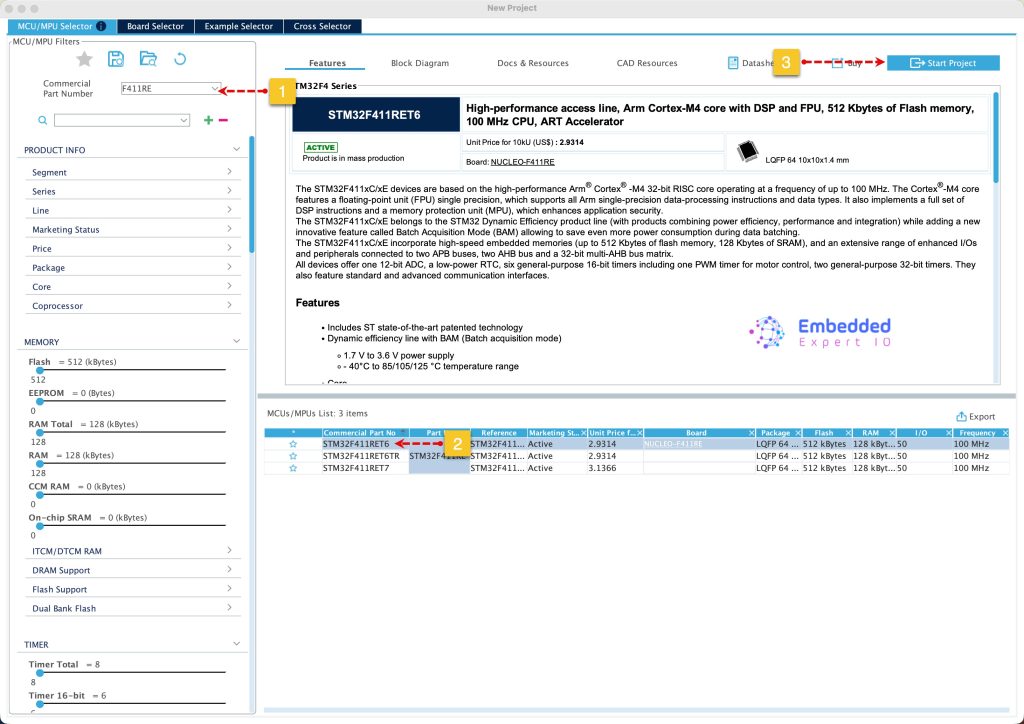
Search for your STM32 MCU, select the MCU and click on Start New Project as follows:
Next, enable USART1 in Asynchronous mode as follows:
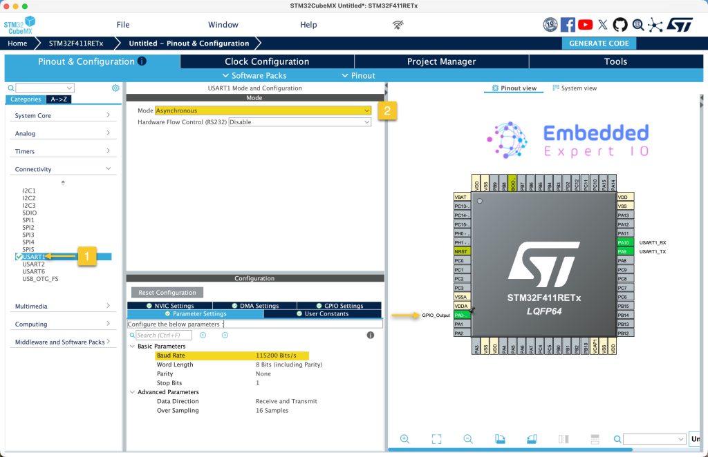
Keep the parameters as is.
Since STM32F411RE which will be the master doesn’t have hardware flow control for RS485, enable GPIO PA0 as output to handle the flow control.
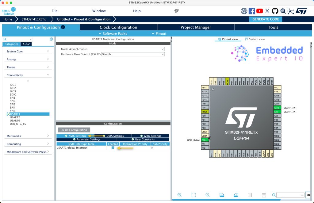
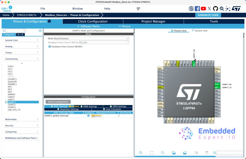
Next, from NVIC settings, enable the interrupt for UASRT as follows:
Next from Project manager tab:
- Give the project a name.
- Set toolchain/IDE to be STM32CubeIDE.
- Click on GENERATE CODE.
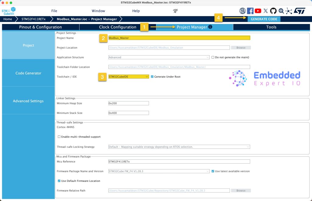
Thats all for master configuration.
4. Slave Configuration:
Open STM32CubeMX as start a new project as follows:
Search for your STM32 MCU, select the MCU and click on Start New Project as follows:

This guide will use STM32L476RG Nucleo-64 board development platform.
Next, once the project has started, select connectivity, then USART1. Set the mode to Asynchronous mode, enable hardware flow control for RS485.
Please note that not all STM32 MCUs have the flow control for RS485
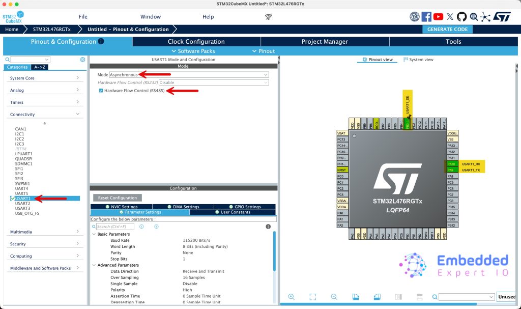
This will configure PA9 and PA10 as USART1_TX and USART1_RX respectively. Also, you set PB3 as the DE signal of RS485 or keep the default one.
Enable the interrupt for USART1 from NVIC settings as follows:
Next, from Project Manager tab:
- Give the project a name.
- Set toolchain/IDE to be STM32CubeIDE.
- Click on GENERATE CODE.
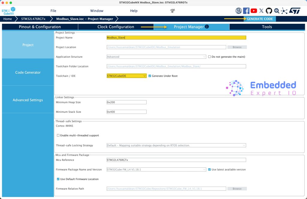
Thats all for the slave configuration.
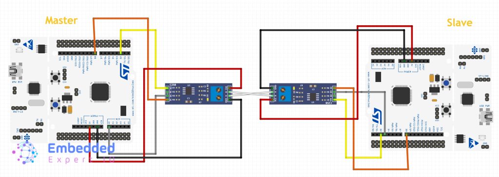
5. Hardware Connection:
The connection as follows:
Next, we shall establish communication between the master and slave.
Stay tuned.
Happy coding 😉
Add Comment