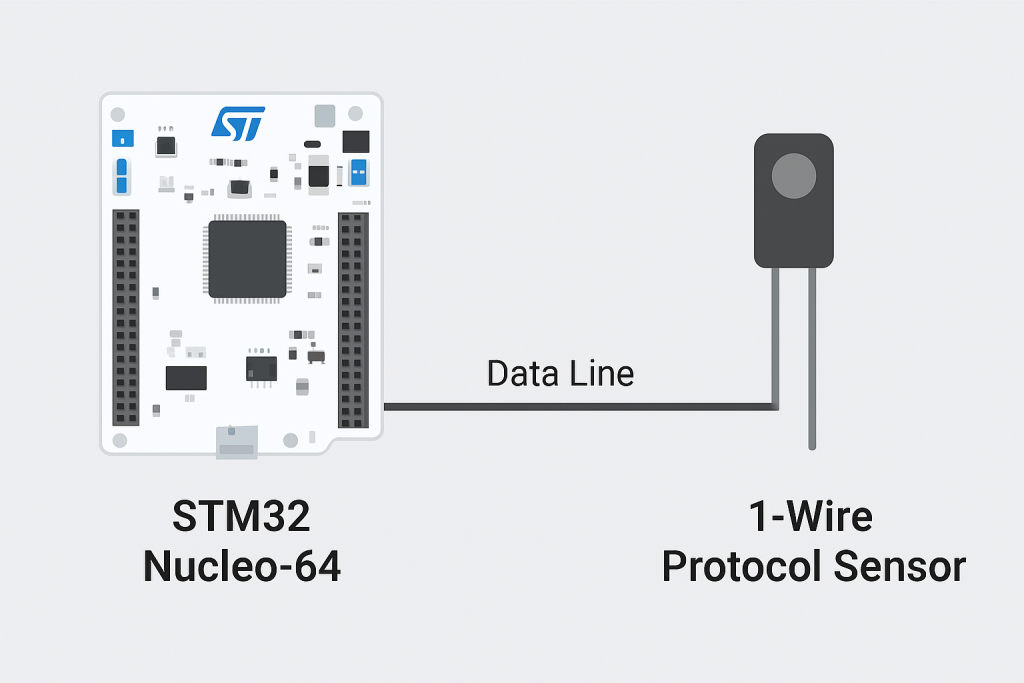
In this part of the guide, we will bring together all the concepts learned so far to measure temperature from the DS18B20sensor using the 1-Wire protocol. You will see how the STM32 communicates with the sensor, initiates a temperature conversion, reads the raw data, and then calculates the precise temperature value in Celsius.
In this guide, we shall cover the following:
- How to reset, send 0 and 1.
- Firmware development.
- Results.
1. How to Reset, Send 0 and 1:
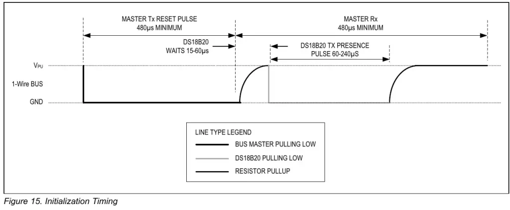
To send the reset condition, the master needs to pull the line low for a minimum of 480us and then release it. When the DS18B20 detects this rising edge, it waits 15μs to 60μs and then transmits a presence pulse by pulling the line low for 60μs to 240μs.
With the baud rate of 115200, the total time taken by 9 bits (Start + 8Data bits) is less than 80us. So we can not possibly pull the line Low continuously for at least 480us. This is why we will use the baud rate of 9600 to send the reset condition.
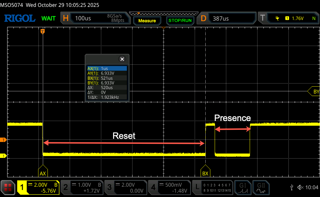
If the master send the byte 0xF0 with the baud rate of 9600, there will be 5 Low bits (Start + 4 Data bits). The total time for which the line will remain low will be around 520us.
Once the sensor detect the reset condition, it will pull the line low for 60 to 240uS, this will inform the master, there is a device. The figure below shows the timing.
By setting the UART baudrate to 9600 and sending 0xF0 via UART, the timing diagram as follows:
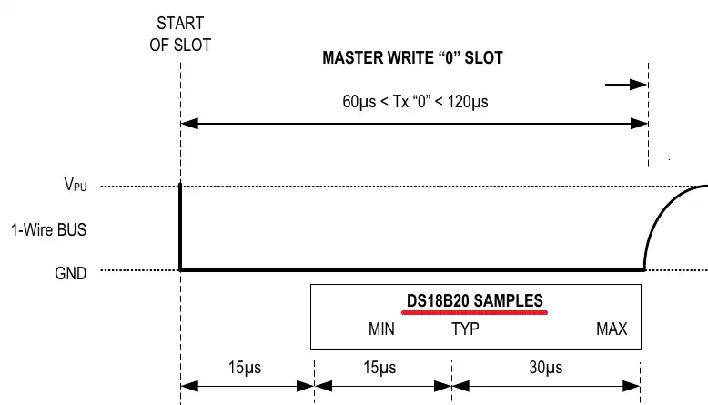
As per the information given in the DS18B20 datasheet, for the sensor to recognize a signal as the bit 0, the data line should transit from HIGH to LOW and then it should be LOW for around 60-120us.
Now if we use the UART at the baud rate of 115200, each bit would take around 8.68us. We are using 8 Data bit, so along with the Start bit we have a total of 9 bits in a single byte. These 9 bits would take around 78us in total.
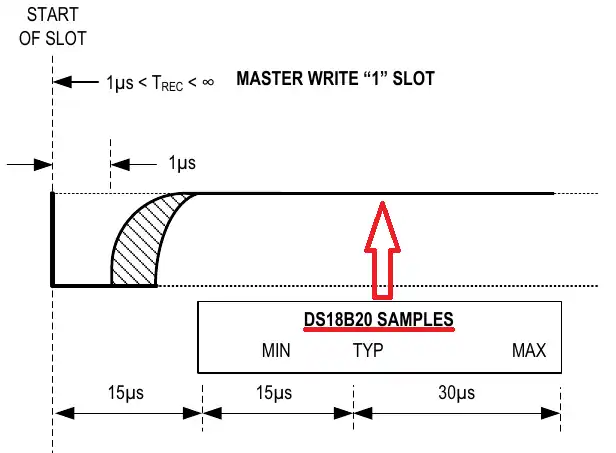
As per the information given in the DS18B20 datasheet, for the sensor to recognize a signal as the bit 1, the data line should transit from HIGH to LOW and then it should be LOW for around 1us. After that the line should be released and the pull up resistor will pull the line High for the rest of the time.
Since each bit at the baud rate of 115200 takes around 8.68us, it is not possible for the MCU to pull the line low for just 1us, it will at least be low for 8.68us.
One interesting point to note is that the DS18B20 sensor does not sample the line immediately after 1us. Instead it will only sample 15us after the line was first pulled low. We will send the data 0xFF, such that only the START bit is low and the rest of the bits are high. This will keep the line low for only around 9-10us and then the line will be pulled High with the help of the pull up resistor.
In short, we need to set the baudrate 10 115200, send 0x00 and 0xFF to represent 0 and 1 respectively.
2. Firmware Development:
First, we need to declare the following variable:
int presence = 0, isRxed = 0;
presence is used during reset (start) condition to detect the presence of the sensor.
isRxed is used when all 8 bytes represent the 8-bit data is received.
Next declare the following variables:
uint8_t RxData[8], Temp_LSB = 0, Temp_MSB = 0;
RxData is used to hold the received data when the sensor sends the temperature data. The data shall be read using DMA.
Next,
int16_t Temp;
This will hold the 16-bit temperature data.
Finally,
float Temperature;
This will provide actual temperature.
Next, declare the following function:
void uart_Init (uint32_t baud)
{
	  huart1.Instance = USART1;
	  huart1.Init.BaudRate = baud;
	  huart1.Init.WordLength = UART_WORDLENGTH_8B;
	  huart1.Init.StopBits = UART_STOPBITS_1;
	  huart1.Init.Parity = UART_PARITY_NONE;
	  huart1.Init.Mode = UART_MODE_TX_RX;
	  huart1.Init.HwFlowCtl = UART_HWCONTROL_NONE;
	  huart1.Init.OverSampling = UART_OVERSAMPLING_16;
	  if (HAL_HalfDuplex_Init(&huart1) != HAL_OK)
	  {
	    Error_Handler();
	  }
}
This function will allow us to change the baudrate during the execution of the code.
Next, declare the following function:
int DS18B20_Start (void)
This function will allow us to send start command as seen in the previous section.
With the function, declare the following:
uint8_t data = 0xF0;
This will hold the data to be transmitted to UART, as we saw, we need to send 0xF0 to get the required delay.
Next, initialize the UART with baudrate of 9600 as follows:
uart_Init(9600);
Next, transmit the data as follows:
HAL_UART_Transmit(&huart1, &data, 1, 100);
Capture the next presence data as follows:
if (HAL_UART_Receive(&huart1, &data, 1, 1000) != HAL_OK) return -1; // failed.. check connection
If the reception failed after 1 second, it means there is no sensor connected, you need to check your connection or the sensor is faulty.
Reinitialize the UART back to 115200 as follows:
uart_Init(115200);
Next, if data ==-2, then there is no device detected:
if (data == 0xf0) return -2; // error no device detected
If it is successful, we shall return 1 as follows:
return 1;
Hence, the function as follows:
int DS18B20_Start (void)
{
	uint8_t data = 0xF0;
	uart_Init(9600);
	HAL_UART_Transmit(&huart1, &data, 1, 100);
	if (HAL_UART_Receive(&huart1, &data, 1, 1000) != HAL_OK) return -1;  // failed.. check connection
	uart_Init(115200);
	if (data == 0xf0) return -2;  // error no device detected
	return 1;
}
Next, the write function:
Declare the function as follows:
void DS18B20_Write (uint8_t data)
Within the function, declare an array to hold the 8 bytes as follows:
uint8_t buffer[8];
Next, we shall construct the array to hold 0 and 1 according to the previous section as follows:
for (int i=0; i<8; i++)
	{
		if ((data & (1<<i)) != 0)  // if the bit is HIGH
		{
			buffer[i] = 0xFF;  // send a 1
		}
		else
		{
			buffer[i] = 0x00;  // send a 0
		}
	}
Finally, transmit the data as follows:
HAL_UART_Transmit(&huart1, buffer, 8, 1000);
Hence, the function as follows:
void DS18B20_Write (uint8_t data)
{
	uint8_t buffer[8];
	for (int i=0; i<8; i++)
	{
		if ((data & (1<<i)) != 0)  // if the bit is HIGH
		{
			buffer[i] = 0xFF;  // send a 1
		}
		else
		{
			buffer[i] = 0x00;  // send a 0
		}
	}

	HAL_UART_Transmit(&huart1, buffer, 8, 1000);
}
Next, the read function.
Declare the following function:
uint8_t DS18B20_Read (void)
Within the function, we shall first declare a buffer as follows:
uint8_t buffer[8];
Declare a variable to hold the read data as follows:
uint8_t value = 0;
Next, fill the buffer with 0xFF to be send to the sensor as follows:
for (int i=0; i<8; i++)
{
  buffer[i] = 0xFF;
}
Send the buffer using DMA as follows:
HAL_UART_Transmit_DMA(&huart1, buffer, 8);
Receive the data using DMA as follows:
HAL_UART_Receive_DMA(&huart1, RxData, 8);
Wait for isRxed to set as follows:
while (isRxed == 0);
Next convert the 8 byte to single byte that represents the original value as follows:
	for (int i=0; i<8; i++)
	{
		if (RxData[i] == 0xFF)  // bit is 1
		{
			value |= 1<<i;  // write a 1 to that position
		}
	}
Next, reset the isRxed as follows:
isRxed = 0;
Return the value as follows:
return value;
Hence, the entire code as follows:
uint8_t DS18B20_Read (void)
{
	uint8_t buffer[8];
	uint8_t value = 0;
	for (int i=0; i<8; i++)
	{
		buffer[i] = 0xFF;
	}

	HAL_UART_Transmit_DMA(&huart1, buffer, 8);
	HAL_UART_Receive_DMA(&huart1, RxData, 8);

	while (isRxed == 0);

	for (int i=0; i<8; i++)
	{
		if (RxData[i] == 0xFF)  // bit is 1
		{
			value |= 1<<i;  // write a 1 to that position
		}
	}

	isRxed = 0;
	return value;
}
Finally, the DMA reception completed callback function:
void HAL_UART_RxCpltCallback(UART_HandleTypeDef *huart)
{
	isRxed = 1;
}
In the while 1 loop.
Start with present detection by sending the start as follows:
presence = DS18B20_Start();
Send skip ROM as follows:
DS18B20_Write(0xCC); // skip ROM
Next, start the temperature conversion as follows:
DS18B20_Write(0x44); // convert t
Send start again:
presence = DS18B20_Start();
Skip ROM again:
DS18B20_Write(0xCC); // skip ROM
Send read scratchpad command
DS18B20_Write(0xBE); // Read Scratchpad
Next, read LSB and MSB of the temperature and construct the 16-bit as follows:
Temp_LSB = DS18B20_Read();
Temp_MSB = DS18B20_Read();
Temp = (Temp_MSB<<8) | Temp_LSB;
Convert the temperature from Temp variable:
Temperature = (float)Temp/16.0; // reslution is 0.0625
Delay by 100ms as follows:
HAL_Delay(100);
Thats all for the project.
3. Results:
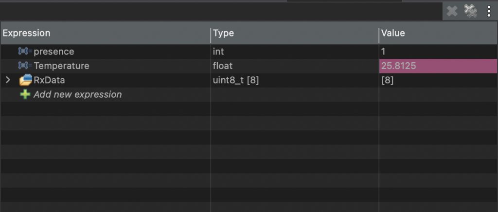
In a debugging session, add Temperature variable to Live Expression
Room temperature:
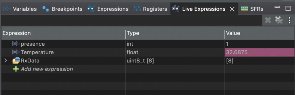
Holding the sensor in my hand:
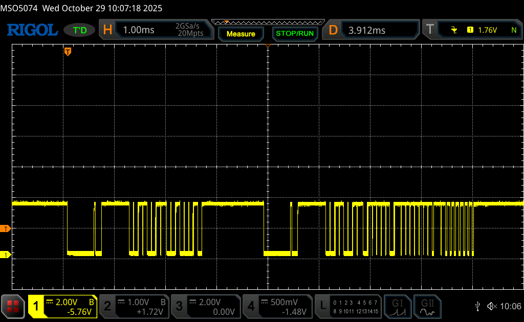
Full communication:
You may download the code from here:
Happy coding 😉
Add Comment