In this part of the guide, the focus is on how the emulated sensor uses interrupts to inform the master about new data availability or status changes. This mechanism mimics real-world sensors that signal the master through dedicated interrupt lines, ensuring timely data acquisition and efficient system operation without continuous polling.
In this guide, we shall cover the following:
- Introduction.
- Hardware connection.
- Emulated sensor firmware.
- Master firmware.
- Results.
1. Introduction:
In embedded systems, allowing an emulated I²C sensor to notify the master through an interrupt instead of relying on constant polling is an important design approach. Real digital sensors, such as accelerometers, gyroscopes, and environmental sensors, often include an interrupt pin that signals the master when new data is available or when a specific event occurs. By having the emulated sensor generate an interrupt, the STM32 slave accurately reproduces the behavior of a real sensor, enabling developers to test and validate the master’s response without the need for physical hardware.
This method eliminates the inefficiency of continuous polling, where the master must repeatedly check for new data, consuming CPU time and bus bandwidth. Instead, the system becomes event-driven—where the master only reacts when needed—making communication more efficient and realistic. Interrupt-based signaling also allows developers to test timing and latency, confirming how quickly the master responds to data-ready events, which is crucial for time-sensitive applications such as motion tracking and control systems.
Moreover, using interrupts supports low-power operation by allowing the master to enter sleep mode until an event occurs. It also enables emulation of complex scenarios, such as multiple interrupt types for different conditions like threshold detection or FIFO overflow. This approach improves firmware robustness by exposing potential weaknesses in interrupt handling, timing, and event prioritization on the master side.
Finally, in real-time systems, the emulated interrupt-driven sensor helps test interrupt latency, priority configuration, and task scheduling to ensure no data is missed under high system load. In summary, interrupt-based communication makes the emulation environment more realistic, efficient, and reliable. It provides developers with a powerful way to validate system performance, timing, and power management before integrating actual hardware sensors.
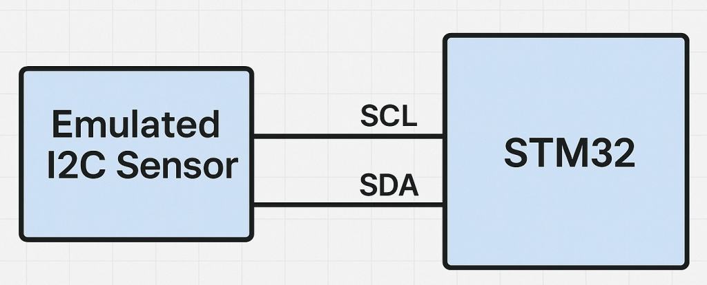
2. Hardware Connection:
The connection as follows:
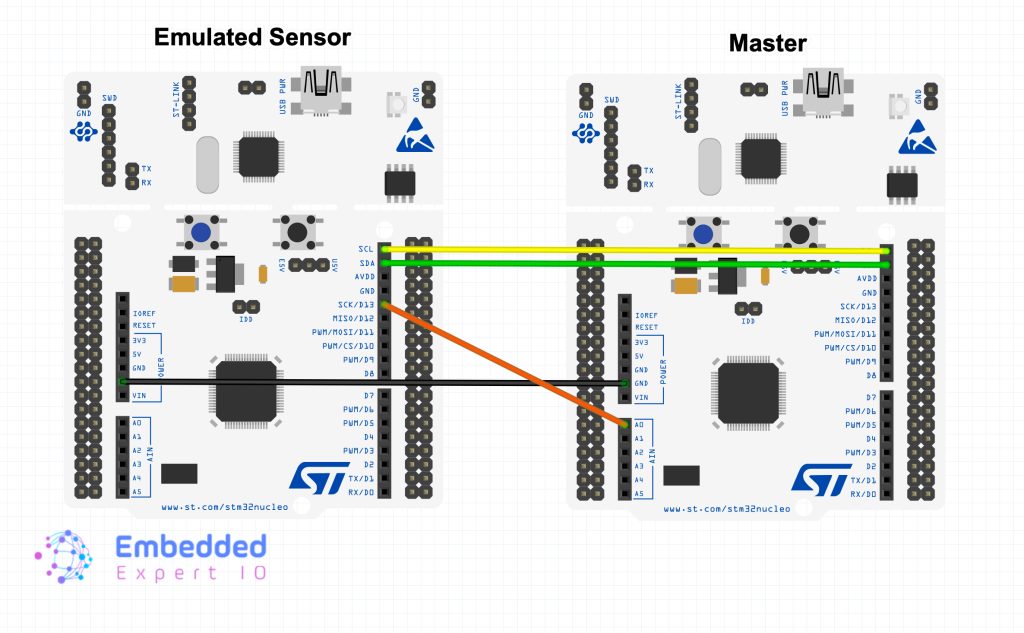
| STM32 Master | Emulated Sensor |
| PB8 (SCL) | PB8 (SCL) |
| PB9 (SDA) | PB9 (SDA) |
| PA0 (EXTI) | PA5 |
| GND | GND |
3. Emulated Sensor Firmware:
Open the slave .ioc file from project explorer. Once the i.oc opened, STM32CubeMX configuration tool will appear.
From Pinout overview, set PA5 as out as follows:
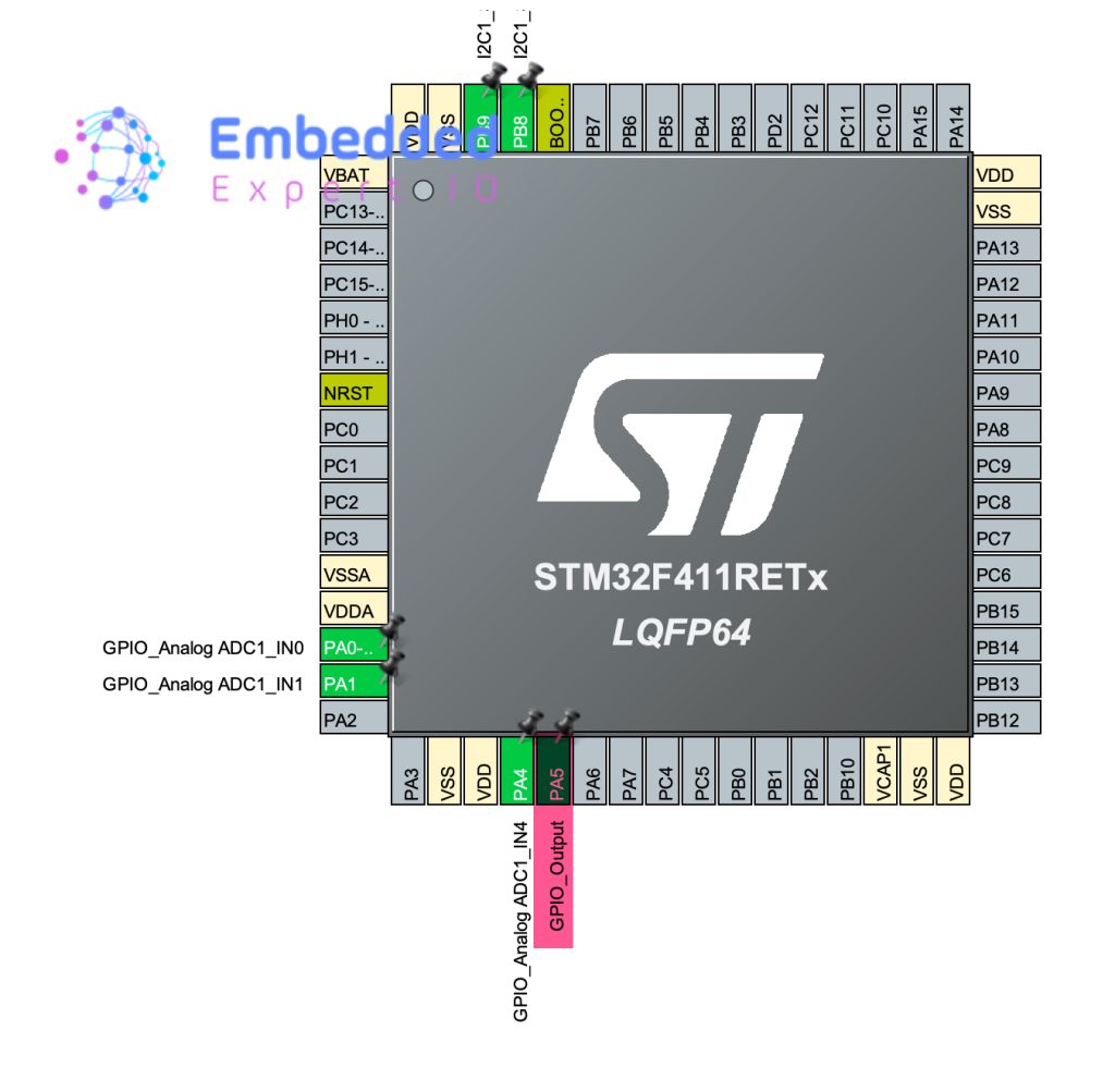
Thats all for the configuration. Save the project, this will generate the code and main.c will be opened.
In main.c in user begin PV, declare a variable:
uint8_t Int_En=0;
This will determine if the user needs to generate interrupt or not. This will be configured in ConfigReg2.
In user code begin 0, add the following code:
void HAL_ADC_ConvCpltCallback(ADC_HandleTypeDef *hadc)
{
	if(hadc->Instance==ADC1)
	{
		if(Int_En==1)
		{
			HAL_GPIO_WritePin(GPIOA, GPIO_PIN_5, GPIO_PIN_SET);
		}
	}
}
This function, HAL_ADC_ConvCpltCallback(), is triggered automatically when the ADC finishes converting an analog signal to a digital value. It checks if the interrupt came from ADC1, and if interrupt generation is enabled (Int_En == 1), it sets GPIOA pin 5 to high. This pin acts as an interrupt output line that notifies the I²C master that new sensor data is ready. In this way, the ADC internal interrupt is used to generate an external interrupt signal to the master, accurately emulating how real sensors indicate that fresh data is available.
In HAL_I2C_AddrCallback function, just before sending ADC data over I2C, add the following:
if(Int_En==1)
{
  HAL_GPIO_WritePin(GPIOA, GPIO_PIN_5, GPIO_PIN_RESET);
}
This will set the INT pin to low once the data register is read.
Hence, the full function as follows:
void HAL_I2C_AddrCallback(I2C_HandleTypeDef *hi2c, uint8_t TransferDirection, uint16_t AddrMatchCode)
{

	if(hi2c->Instance==I2C1)
	{

		if(TransferDirection==I2C_DIRECTION_TRANSMIT)
		{

			HAL_I2C_Slave_Seq_Receive_IT(hi2c, RegisterData, 2, I2C_FIRST_FRAME);

		}

		else
		{
            if (RegisterData[0] == ReadReg1)   // <-- prepare fresh data here
            {
                SensorData[0] = ADC_Data[0];
                SensorData[1] = ADC_Data[1];
                SensorData[2] = ADC_Data[2];
            }
            if(Int_En==1)
            {
            	HAL_GPIO_WritePin(GPIOA, GPIO_PIN_5, GPIO_PIN_RESET);
            }
			HAL_I2C_Slave_Seq_Transmit_IT(hi2c,SensorData, 3, I2C_FIRST_AND_LAST_FRAME);
		}


	}

}
In HAL_I2C_SlaveRxCpltCallback where we configure the registers, we shall configure if the interrupt generation is needed as follows:
else if (CurrentRegister == ConfigReg2)
            {
                ConfigReg2Value = RegisterData[1];

                if(ConfigReg2Value==1)
                {
                	Int_En=1;
                }
                else
                {
                	Int_En=0;
                }

            }
This will configure if interrupt is needed or not.
Hence, the full function as follows:
void HAL_I2C_SlaveRxCpltCallback(I2C_HandleTypeDef *hi2c)
{
    if (hi2c->Instance == I2C1)
    {

            CurrentRegister = RegisterData[0]; // first byte = register

            if (CurrentRegister == ConfigReg1)
            {
                switch ( RegisterData[1])
                {
                	case 0: __HAL_TIM_SET_AUTORELOAD(&htim2, 100-1);
                		break;
                	case 1: __HAL_TIM_SET_AUTORELOAD(&htim2, 50-1);
                		break;
                	case 2: __HAL_TIM_SET_AUTORELOAD(&htim2, 10-1);
                		break;
                	default: __HAL_TIM_SET_AUTORELOAD(&htim2, 100-1);
                		break;

                }
            }
            else if (CurrentRegister == ConfigReg2)
            {
                ConfigReg2Value = RegisterData[1];

                if(ConfigReg2Value==1)
                {
                	Int_En=1;
                }
                else
                {
                	Int_En=0;
                }

            }
    }


}
Thats all for the emulated sensor. Save the project and run it on your board.
4. Master Configuration:
Open the master .ioc file from project explorer. Once the i.oc opened, STM32CubeMX configuration tool will appear.
From pinout overview, set PA0 as EXTI0 as follows:
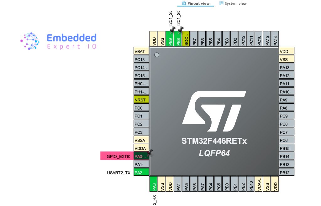
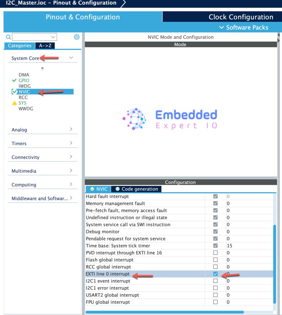
Next, from System Core, NVIC, enable EXTI line 0 interrupt as follows
Thats all for the configuration, save the project and this will generate the code and main.c shall be opened.
In main.c in user code begin PV, declare the following:
volatile uint8_t newData=0;
This is a flag which tell our mcu that there is an interrupt from the sensor and need to process it.
In user code begin code 0, declare the following:
void HAL_GPIO_EXTI_Callback(uint16_t GPIO_Pin)
{
	if(GPIO_Pin==GPIO_PIN_0)
	{
		newData=1;
	}
}
This function will be called when EXTI is happens.
In the function, we need to determine which pin it is, since it is PA0, we shall use GPIO_PIN_0 and set the flag to 1.
In user code begin 2 in main function:
/*Set sample rate to 100ms*/
SlaveData[0]=0x00;
SlaveData[1]=2;
HAL_I2C_Master_Transmit(&hi2c1, (0x1D<<1), SlaveData, 2, 100);

/*Enable interrupt generation*/
SlaveData[0]=0x01;
SlaveData[1]=1;
HAL_I2C_Master_Transmit(&hi2c1, (0x1D<<1), SlaveData, 2, 100);
In while 1 loop:
/*Read the sensor*/
if(newData==1)
{
  HAL_I2C_Mem_Read(&hi2c1, (0x1D<<1), 0x03, 1, SensorData, 3, 100);
  newData=0;
}
That all for the master configuration. Save the project and start a debugging session as follows:

5. Results:
By adding SensorData to Live expressions in the debugging session, you should get 3 ADC as follows:
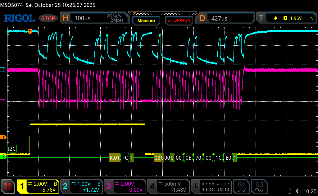
Here is a sample for i2c bus with interrupt.
When line goes from 0 to 1, an interrupt is generated in the master and start the reading sequence.
Notice that once the master requests read from a register, the pin goes immediately to low and send the ADC data.
Thats all for sensor emulation.
Happy coding 😉
Add Comment