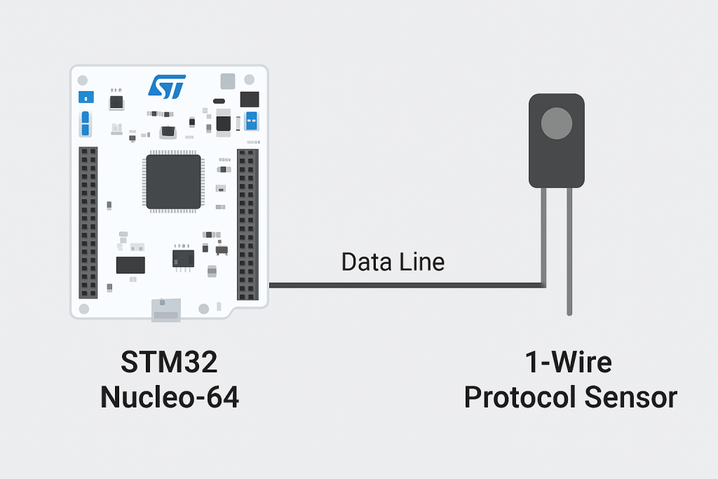
In this two-part guide, we explore how to interface the DS18B20 temperature sensor with an STM32 microcontrollerusing the 1-Wire communication protocol. The first part introduces the fundamentals of the 1-Wire protocol, explains how the DS18B20 operates, and walks through the essential environment setup for STM32 development.
In this guide, we shall cover the following:
- What is 1-wire protocol.
- DS18B20 temperature sensor.
- Hardware setup.
- STM32CubeIDE setup.
1. What is 1-Wire Protocol:
The 1-Wire protocol is a serial communication standard developed by Dallas Semiconductor (now Maxim Integrated)that enables data exchange between a single master device (such as an STM32 microcontroller) and one or more slave devices (such as sensors or memory ICs) over a single data line plus ground. Unlike protocols such as SPI or I²C that require multiple signal lines for data and clock, 1-Wire uses just one wire for both communication and, optionally, power delivery (in parasitic power mode), making it one of the simplest and most efficient communication systems for low-cost embedded designs.
Core Concept
At its core, 1-Wire communication is asynchronous and half-duplex, meaning data can travel in both directions, but only one direction at a time. All devices share the same bus, and the master controls all communication timing. Each slave device has a unique, factory-programmed 64-bit address, which ensures global uniqueness and allows the master to identify and communicate with specific devices even when many are connected on the same line.
The bus operates with open-drain signaling, where devices can only pull the line low — never drive it high. A pull-up resistor (typically 4.7 kΩ) keeps the line high when no device is pulling it low. This design allows multiple devices to coexist without bus contention and also enables parasitic powering.
Electrical Characteristics
- Single data line: Used for both data transmission and power (optional).
- Pull-up resistor: Keeps the line idle high; required for proper communication.
- Logic levels: Typically 0 V for logic ‘0’ and 3.3 V/5 V for logic ‘1’.
- Speed: Standard mode at 16.3 kbps; Overdrive mode at 142 kbps.
- Bus topology: Supports linear, star, and mixed configurations up to several tens of meters (depending on capacitance and wiring quality).
Communication Sequence
- Reset pulse (Initialization):
- The master pulls the line low for at least 480 µs to reset all slaves.
- Slaves respond with a presence pulse (holding the line low for 60–240 µs) to signal they are active.
- ROM Commands:
These commands are used to identify or address devices on the bus. Examples include:- Read ROM (0x33): Read the 64-bit unique ID of a single connected device.
- Match ROM (0x55): Select a specific device using its unique address.
- Search ROM (0xF0): Discover all devices connected to the bus.
- Skip ROM (0xCC): Address all devices simultaneously (useful when only one device is connected).
- Function Commands:
Once a specific device is addressed, function commands are used to perform device-specific actions such as reading sensor data, writing memory, or configuring parameters.
Timing and Bit Transmission
Each bit (logical ‘0’ or ‘1’) is represented by timing differences in how long the data line stays low or high:
- Write ‘1’: Master pulls the line low for ~6 µs, then releases it to let it stay high for the rest of the 60 µs time slot.
- Write ‘0’: Master pulls the line low for ~60 µs, then releases it briefly before the next bit.
- Read Bit: Master pulls the line low for ~6 µs, releases it, and reads the line state after ~15 µs to sample the bit value sent by the slave.
Accurate timing is critical — even small deviations can corrupt communication. This is why precise delay functions or hardware peripherals (like UART in half-duplex mode or timers) are often used to emulate the 1-Wire protocol on STM32.
Parasitic Powering
One of the most distinctive features of 1-Wire devices is parasitic power mode. In this mode, the slave draws power directly from the data line when it is high, storing energy in an internal capacitor to operate when the line is low. This allows devices like the DS18B20 to run with only two connections — data and ground, eliminating the need for a separate power line.
However, parasitic power limits the available current and may not be suitable for high-current operations or long cable runs. In such cases, a dedicated power pin (VDD) can be used.
Multi-Device Bus and Unique Identification
Each 1-Wire device includes a globally unique 64-bit ROM code structured as follows:
- 8-bit family code (identifies device type, e.g., temperature sensor, memory)
- 48-bit serial number (unique identifier)
- 8-bit CRC for error checking
This makes it possible for a single master to enumerate and communicate with hundreds of devices on one shared line without conflicts. Devices can be dynamically added or removed without reconfiguration.
Advantages of the 1-Wire Protocol
Minimal wiring — just one data line plus ground.
Globally unique IDs for every device.
Low hardware cost and easy scalability.
Parasitic power option for truly minimal connections.
Multi-drop support — multiple devices on one bus.
Limitations
Low communication speed compared to I²C or SPI.
Strict timing requirements, often requiring precise microcontroller control or hardware timers.
Limited cable length and capacitance tolerance, which may affect reliability in large networks.
No hardware 1-Wire interface on most MCUs (implemented in software).
Typical Applications
- Temperature sensing (e.g., DS18B20, DS1822)
- Identification and authentication (e.g., iButton devices)
- EEPROM memory storage (e.g., DS2431)
- Battery monitoring
- Industrial sensor networks
2. DS18B20 Temperature Sensor:
The DS18B20 is a digital temperature sensor developed by Dallas Semiconductor (now Maxim Integrated) that measures temperature with high accuracy and communicates using the 1-Wire protocol. It is one of the most popular and widely used temperature sensors in embedded systems because of its simplicity, accuracy, and versatility.
Unlike analog temperature sensors (such as LM35 or TMP36), the DS18B20 provides a digital output — no need for analog-to-digital conversion. This makes it ideal for microcontrollers like STM32, which can directly read temperature data through a single GPIO pin using software or hardware-driven 1-Wire communication.
Key Features
| Feature | Description |
|---|---|
| Interface | 1-Wire protocol (single data line for communication and optional power) |
| Temperature range | –55 °C to +125 °C |
| Accuracy | ±0.5 °C (–10 °C to +85 °C) |
| Resolution | Configurable: 9-bit to 12-bit |
| Power supply | 3.0 V to 5.5 V |
| Parasitic power | Supported (can operate without dedicated VDD) |
| Unique ID | Each device has a factory-programmed 64-bit ROM code |
| Communication speed | Standard (16.3 kbps) and Overdrive (142 kbps) modes |
| Package options | TO-92, waterproof probe, SMD, or custom PCB modules |
Internal Structure and Operation
The DS18B20 consists of several internal blocks:
- Temperature Sensor and ADC
- The sensor measures temperature using an internal silicon bandgap sensor.
- The analog signal is converted to a digital 16-bit value using an internal ADC.
- Resolution is configurable between 9-bit (0.5 °C steps) and 12-bit (0.0625 °C steps).
- Scratchpad Memory
- A temporary 9-byte memory area that stores temperature readings, user settings, and configuration data.
- It can be read or written by the master device.
- EEPROM
- Used to store the high/low temperature thresholds and resolution configuration permanently.
- Unique 64-bit ROM
- Each device has a globally unique ROM code, which consists of:
- 8-bit Family Code (0x28 for DS18B20)
- 48-bit Serial Number
- 8-bit CRC
- This allows multiple DS18B20 sensors to share the same 1-Wire bus.
- Each device has a globally unique ROM code, which consists of:
- 1-Wire Interface Logic
- Handles all communication, including reset detection, bit timing, and CRC verification.
Powering Modes
1. Normal Power Mode
- The sensor is powered through the VDD pin (3.0 – 5.5 V).
- The data line is only used for communication.
- This mode is the most stable and is recommended when a dedicated power line is available.
2. Parasitic Power Mode
- The VDD pin is connected to ground, and the device draws power directly from the data line through an internal diode and capacitor.
- The capacitor charges when the line is high, and powers the device when the line is pulled low.
- This enables operation with only two connections (DQ and GND).
- However, it requires a strong pull-up on the data line during temperature conversion and EEPROM writes.
Communication Overview
The DS18B20 communicates through the 1-Wire protocol, controlled entirely by the master (e.g., STM32). The master initiates all operations, and the sensor only responds when addressed.
A typical communication cycle includes:
- Initialization (Reset and Presence Pulse)
- The master pulls the data line low for ≥480 µs to reset all devices.
- After release, each connected device responds with a presence pulse (low for 60–240 µs).
- ROM Commands
- Used to identify or address individual sensors.
- Key ROM commands:
0x33— Read ROM (read the device’s 64-bit address)0x55— Match ROM (address a specific device)0xCC— Skip ROM (address all devices)0xF0— Search ROM (enumerate devices on the bus)
- Function Commands
- After selecting a device, function commands control operations like temperature measurement and data reading.
- Common commands:
0x44— Convert T (start temperature conversion)0xBE— Read Scratchpad (read temperature and settings)0x4E— Write Scratchpad (set thresholds and resolution)0x48— Copy Scratchpad (store thresholds/resolution to EEPROM)0xB8— Recall EEPROM (restore saved settings)0xB4— Read Power Supply (detect if powered parasitically)
Temperature Conversion and Data Format
When the master issues the Convert T (0x44) command, the DS18B20 measures the current temperature and stores the result in the scratchpad.
Conversion Time
The conversion time depends on resolution:
| Resolution | Bits | Time (Typical) | Step Size |
|---|---|---|---|
| 9-bit | 93.75 ms | 0.5 °C | |
| 10-bit | 187.5 ms | 0.25 °C | |
| 11-bit | 375 ms | 0.125 °C | |
| 12-bit | 750 ms | 0.0625 °C |
Scratchpad Memory Layout (9 Bytes)
| Byte | Purpose | Example |
|---|---|---|
| 0 | Temperature LSB | 0x50 |
| 1 | Temperature MSB | 0x05 |
| 2 | TH (High Alarm Trigger) | User-defined |
| 3 | TL (Low Alarm Trigger) | User-defined |
| 4 | Configuration Register | Resolution bits (R1, R0) |
| 5–7 | Reserved | Internal use |
| 8 | CRC | For data integrity check |
Temperature Data Format
Temperature is stored as a signed 16-bit two’s complement value:
T = Raw Data* 0.0625°C
Device Addressing and Multi-Sensor Systems
Since every DS18B20 has a unique 64-bit ROM, multiple sensors can share the same data line. The master can:
- Use Search ROM (0xF0) to enumerate all sensors.
- Use Match ROM (0x55) to communicate with a specific sensor.
- Use Skip ROM (0xCC) if only one device is connected.
This makes the 1-Wire bus incredibly scalable — dozens of sensors can measure temperature at different points using a single microcontroller pin.
Applications
The DS18B20 is used in a wide range of environments due to its robustness, accuracy, and digital simplicity:
- HVAC systems
- Industrial process monitoring
- Weather stations
- Smart thermostats and home automation
- Medical temperature probes
- Battery management systems
- Embedded system diagnostics
Advantages and Limitations
| Advantages | Limitations |
|---|---|
| Requires only one data line | Communication speed is slow |
| Each sensor has a unique ID | Timing-critical protocol |
| No ADC required (digital output) | Needs precise pull-up resistor and timing control |
| Operates in wide voltage range | Limited cable length (capacitance-sensitive) |
| Supports multiple sensors on one bus | Parasitic power limits current and cable distance |
3. Connection:
The connection as follows:
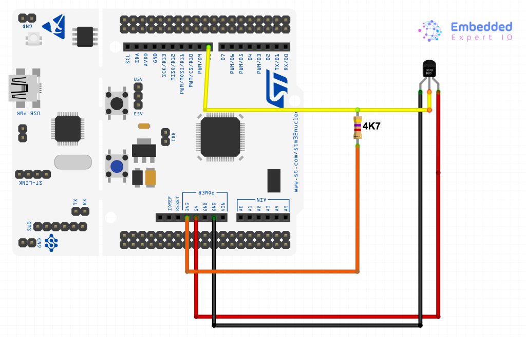
| SD18B20 | STM32F411RE Nucleo-64 |
| Vcc | 5V |
| DIO | PA9 (D8 of Arduino pin) |
| GND | GND |
Also, connect a pull up resistor between DIO and 3V3.
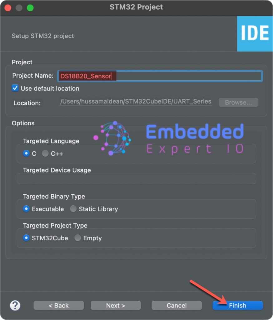
4. STM32CubeIDE Setup:
Open STM32CubeIDE after selecting the workspace and create new project as following:

Select the MCU:

Give the project a name and click on finish:
Once the project has been created, STM32CubeMX shall appear.
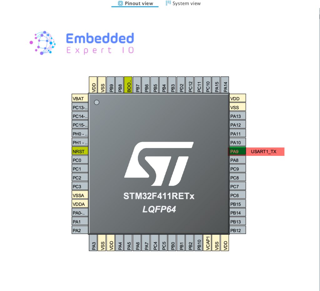
From connectivity, select USART1 (Or any other serial you want) and set the mode as Single-Wire (Half-duplex) as follows:
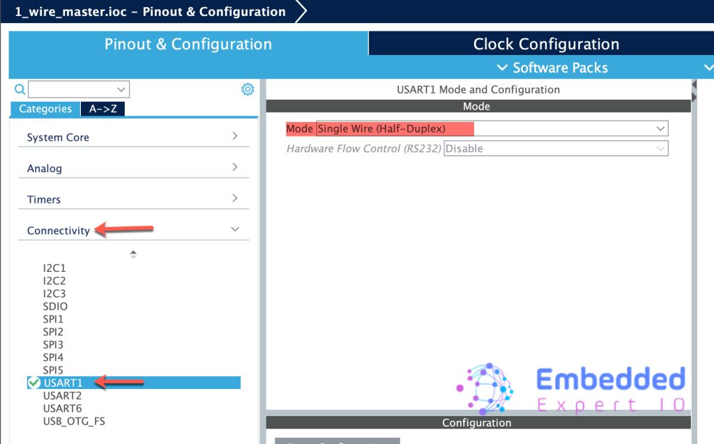
This wil set PA9 as UART1_TX pin as follows:
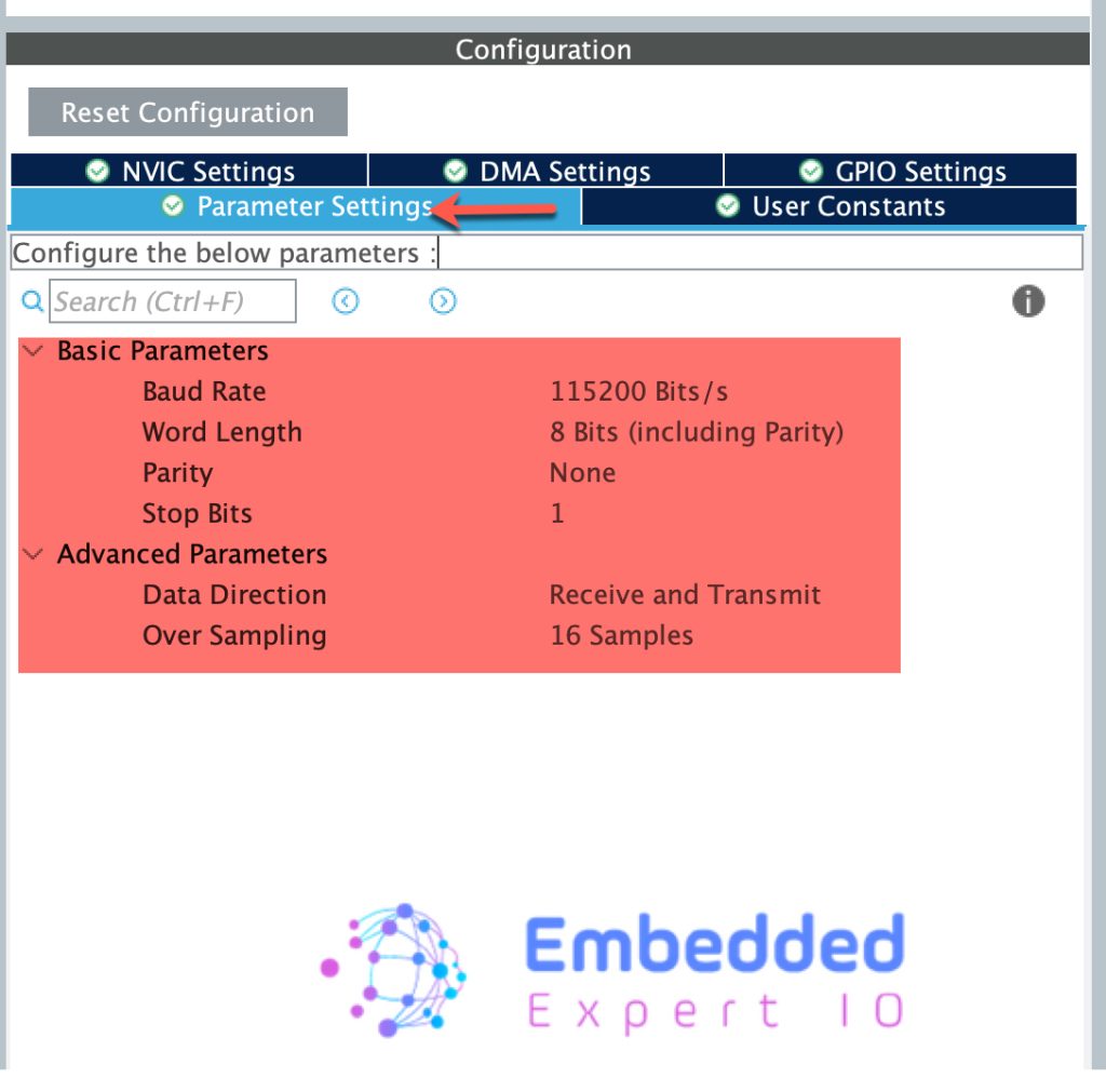
In the configuration, leave everything as is since we shall change the UART configuration according to our needs.
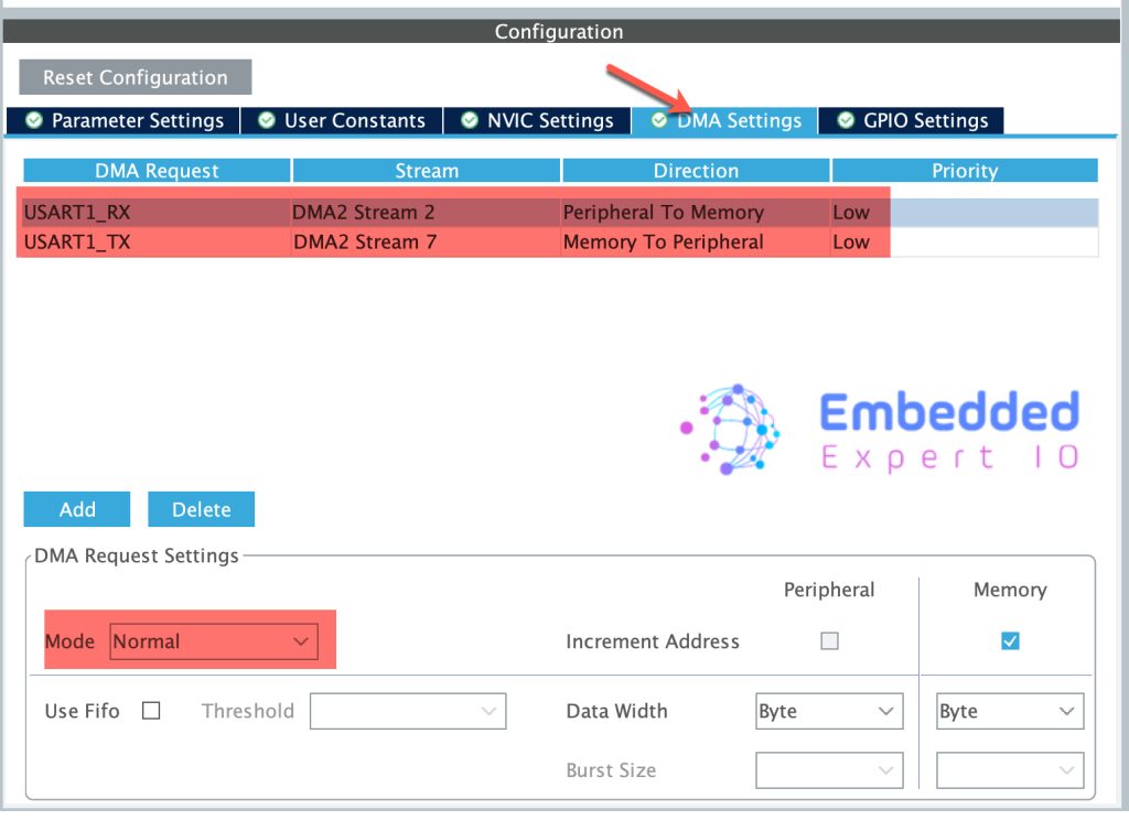
Next, from DMA settings, add DMA for TX and RX as follows:
Thats all for the configuration.
Save the project and this will generate the code.
In part 2, we shall dig deeper into DS18B20 communication.
Stay tuned.
Happy coding 😉
Add Comment