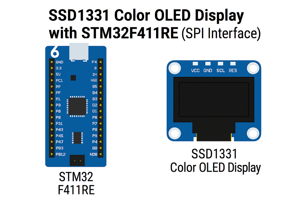
This guide walks you through working with the SSD1336 SPI color OLED display using STM32 MCUs. In part one, we’ll cover the SSD1331 controller basics, environment setup, and hardware connections to get started.
In this guide, we shall cover the following:
- Introduction.
- SSD1331 controller.
- Hardware Connection.
- STM32CubeIDE setup.
1. Introduction:
Organic Light Emitting Diode (OLED) displays have become an essential part of modern embedded systems due to their high contrast ratio, wide viewing angles, vibrant colors, and relatively low power consumption compared to traditional LCDs. Among the many OLED driver ICs available, the SSD1331 is a popular controller designed for color OLED panels with SPI and parallel interface options. It provides efficient control over pixel rendering, brightness, contrast, and display memory organization, making it well-suited for compact embedded applications such as handheld devices, IoT modules, instrumentation panels, and wearable electronics.
In this guide, we will focus on using the SSD1331 with an STM32 microcontroller over the SPI interface. The SSD1331 controller manages the communication between the microcontroller and the OLED panel by handling pixel data, color encoding, command sets, and display memory addressing. It supports essential features like display on/off control, sleep modes, horizontal and vertical addressing, and partial updates, which make it versatile for both static images and dynamic graphical interfaces. Understanding the SSD1331 command set and initialization sequence is a crucial first step toward achieving reliable display operation.
To follow along with this guide, we will prepare a suitable development environment based on the STM32 ecosystem. The STM32 family, built on Arm Cortex-M cores, is widely used for display-based applications due to its performance, peripheral availability, and extensive software support. We will set up the environment using STM32CubeIDE (an all-in-one development platform from STMicroelectronics) along with the HAL drivers for SPI and GPIO peripherals. This setup will allow us to efficiently manage communication with the SSD1331 controller, send commands, and later extend functionality to graphics libraries.
Alongside the software environment, the hardware setup must also be clearly understood before diving into display programming. The SSD1331 OLED module typically exposes an SPI interface with pins for MOSI (data), SCK (clock), CS (chip select), DC (data/command), RST (reset), and power supply lines. On the STM32 side, we will configure one of its hardware SPI peripherals along with GPIOs for control signals. Special attention must be given to voltage levels (3.3V operation is typical for both STM32 and SSD1331 modules), power sequencing, and reset handling to ensure stable operation. Proper wiring and grounding are essential to avoid noise-related artifacts on the display.
In this first part of the guide, we will therefore cover three key areas:
- The SSD1331 Controller – Overview of features, internal architecture, memory organization, and command system.
- Environment Setup – Installing and configuring STM32CubeIDE, initializing SPI with HAL, and preparing the project workspace.
- Hardware Setup – Wiring the SSD1331 OLED to STM32, understanding pin functions, power requirements, and recommended connections for stable display operation.
By the end of this section, you will have both the theoretical foundation and the hardware environment ready, so that in the next dedicated section we can focus on developing the firmware to initialize the display, send commands, and render test patterns.
2. SSD1331 Controller:
The SSD1331 Controller
The SSD1331 is a high-performance OLED driver IC from Solomon Systech, designed to control small-sized full-color OLED panels. Unlike monochrome OLED controllers, the SSD1331 is tailored for RGB displays and includes built-in graphic acceleration functions, making it easier and faster to render shapes, fill areas, and display images. This makes it especially useful for embedded systems that need a compact but visually rich interface.
1. Key Features
- Resolution Support: Optimized for 96 × 64 pixel color OLED panels.
- Color Depth: Supports up to 65,536 colors (16-bit RGB565 format) and 262,144 colors (18-bit RGB666 format).
- Interface: 8-/9-bit parallel or 4-wire SPI, suitable for both high-speed and low-pin-count applications.
- Graphic Acceleration: Hardware support for line drawing, rectangle filling, copy/scrolling, and other geometric operations, reducing MCU workload.
- GDDRAM: Built-in display RAM stores pixel data for the full screen, eliminating the need for continuous MCU refresh.
- Display Control: Functions for inversion, partial display, power save modes, and programmable contrast/brightness.
- Integrated Timing Generator: Handles scanning and refresh cycles for stable display output.
2. Internal Architecture
The SSD1331 integrates the following major blocks:
- Command Decoder – Interprets instructions from the host MCU.
- Graphic Display Data RAM (GDDRAM) – Stores the full-screen pixel data in RGB format.
- Graphic Acceleration Engine – Executes drawing commands like line, rectangle, or fill directly in hardware.
- Timing Controller (TCON) – Generates the scan signals for the OLED panel.
- Common/Segment Drivers – Drive the OLED matrix rows and columns.
- Power Circuits & Oscillator – Provide regulated voltages and timing for stable operation.
3. Memory Organization
For a 96 × 64 display, the GDDRAM is organized as a 96 (columns) × 64 (rows) matrix of pixels, with each pixel requiring:
- 16-bit (2 bytes) in RGB565 format, or
- 18-bit (3 bytes) in RGB666 format.
In practice, most applications use RGB565 due to reduced data transfer overhead and wide library support.
4. Command Set Overview
The SSD1331 supports both standard OLED control commands and enhanced graphic instructions. Some important commands include:
- Display ON/OFF – Enable or disable the screen.
- Set Column/Row Address – Define the drawing window.
- Write RAM – Transfer pixel data into GDDRAM.
- Set Contrast (per RGB channel) – Adjust brightness individually for red, green, and blue.
- Set Display Mode – Normal, inverted, or sleep modes.
- Graphic Commands:
- Draw Line (start X,Y → end X,Y)
- Draw Rectangle (with optional fill color)
- Copy / Move block of pixels
- Fill rectangle area with color
These hardware-accelerated functions can dramatically improve rendering speed compared to sending pixel data one by one.
3. Hardware Setup:
The connection as follows:
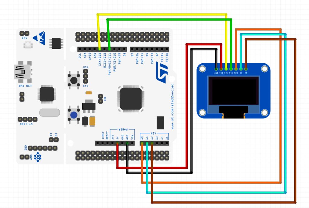
| SSD1331 OLED Display | STM32F411 Nucleo-64 |
| GND | GND |
| Vcc | 5V |
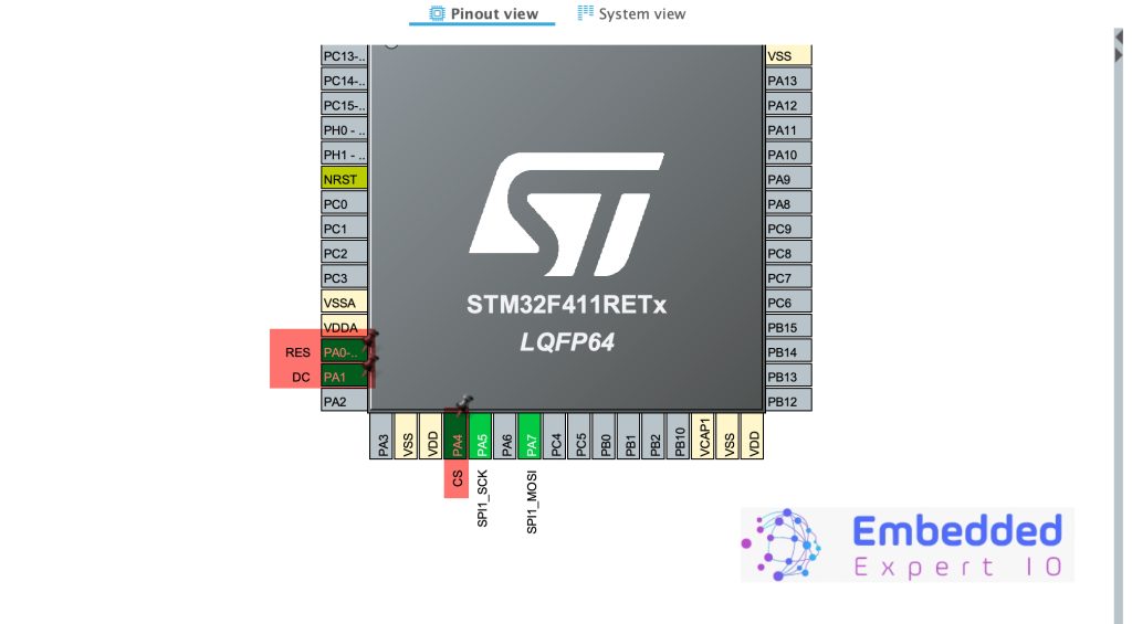
| SCK | PA5 (D13 Arduino pin) |
| SDA | PA7 (D11 Arduino Pin) |
| RES | PA0 (A0 Arduino Pin) |
| DC | PA1 (A1 Arduino Pin) |
| CS | PA4 (A2 Arduino Pin) |
4. STM32CubeIDE Setup:
Open STM32CubeIDE after selecting the workspace and create new project as following:

Select the MCU:

Give the project a name:
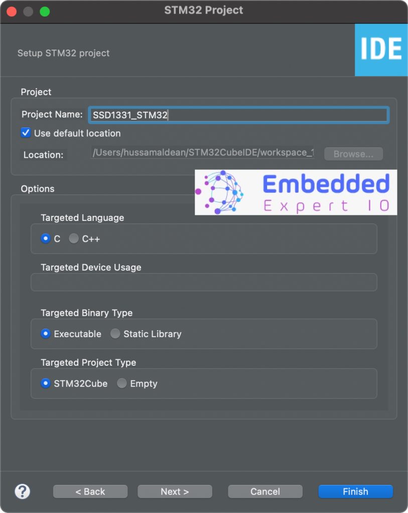
Make sure the Targeted Project Type is STM32Cube, Language is C and binary type is Executable.
Next, head to connectivity, SPI1 and enable it in Transmit Only Master mode.
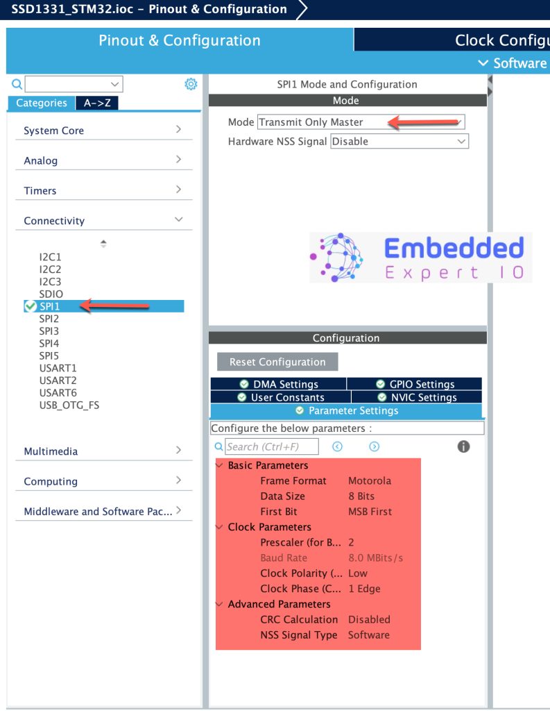
Keep the parameters as is. Just make sure the data size is 8-bit and maximum speed is 8 to 10MHz.
Next, enable the DMA for SPI as follows:
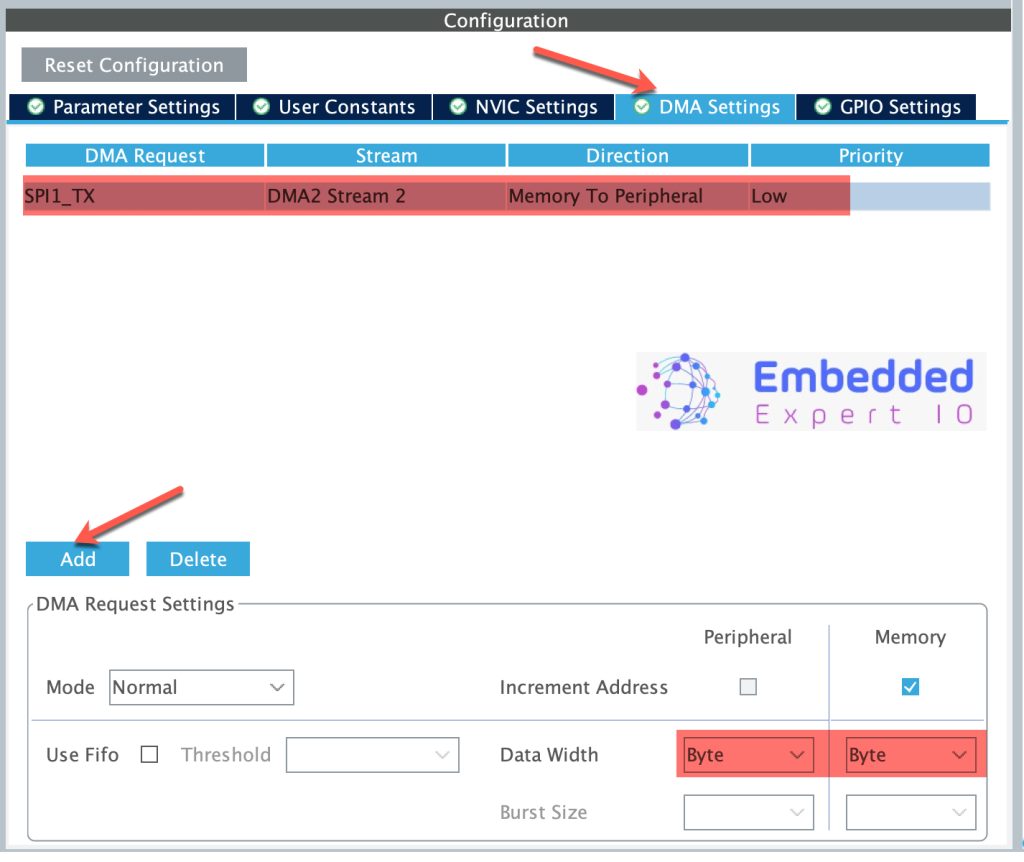
Set the mode to Normal, data width to byte for both memory and peripheral.
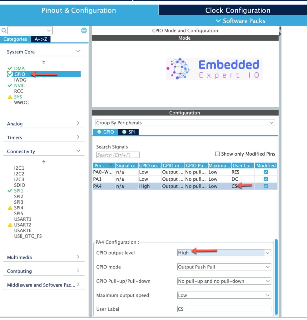
Set PA0, PA1 and PA4 as GPIO output and give them a name as mentioned in the hardware setup as follows:
Next, head to GPIO, select CS pin and set GPIO output level to High as follows:
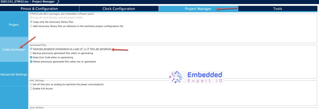
Last step, head to Project Manager, Code Generator then generate peripheral initialization as pair of .c/.h as follows:
Save the project and this will generate the project.
In part 2, we shall start developing the library and write to the lcd.
Stay tuned.
Happy coding 😉
Add Comment