
In previous guide (here) we discussed how to handle Systick timer interrupt and blink a single led using interrupt generated by systick and millis function. In this guid, we will take it even further by blinking multiple leds (3 leds) in interrupt itself rather externally and one using crude inefficient delay to demonstrate the capability of interrupt.
In this guide will cover the following:
- Locating LEDs in STM32F407 Discovery board
- Configuring GPIO and Systick timer
- Code
1. Locating LEDs in STM32F407 Discovery Board
In this guide, we shall use STM32F407Discovery (Link), since it has 4 built-in leds which fit perfectly for this experiment.
According to this evaluation board user manual (link), the leds are connected to the following GPIO-pins:
| LED color | Port connected to |
| Orange | PD13 |
| Green | PD12 |
| Red | PD14 |
| Blue | PD15 |
From the table we concluded that the LEDs are connected to PORTD.
2. Configuring GPIO and SysTick
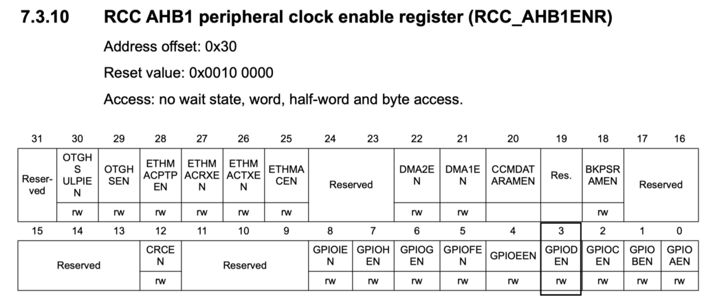
To enable clock access to GPIOD we need to set bit 3 from AHB1ENR register show here.
After enabling the clock, we need to set PD12, 13, 14 and 15 as output.
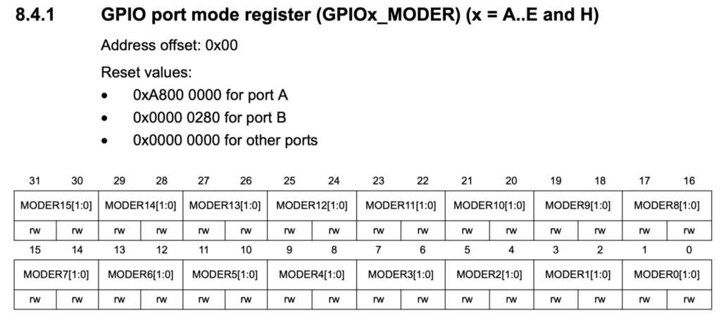
In order to configure the pins as output, we need set bits 24, 26, 28 and 30.
For configuring Systick timer, it will be as following:
- Disable Systick Timer (SysTick->CTRL=0;).
- load value 16000-1 for 1mS operation (SysTick->LOAD=16000-1;).
- Select clock source to processor clock, enable interrupt and start counter (SysTick->CTRL=7;)
3. Code
#include "stm32f4xx.h"
// clock access to GPIOD
#define GPIOD_CLOCK    (1<<3)
//bits of the pins
#define LED_red_BIT    (1U<<28)
#define LED_green_BIT  (1U<<24)
#define LED_orange_BIT (1U<<26)
#define LED_blue_BIT   (1U<<30)
//LED port
#define	LED_PORT		    GPIOD
//bit possition for color
#define	LED_red		 		 (1U<<14)
#define LED_green  		 (1U<<12)
#define LED_blue       (1U<<15)
#define LED_orange     (1U<<13)
//blinking rate
#define Rate_green      200
#define Rate_blue       500
#define Rate_orange     1000
//variable to store time in milliseconds
volatile uint64_t ms;

//ineffecient delay prototype
void delay(int delayms);

int main(void)
{
//enable GPIO clock, configure pins as output and systick
__disable_irq();
RCC->AHB1ENR |=GPIOD_CLOCK;
GPIOD->MODER |= LED_red_BIT|LED_green_BIT|LED_orange_BIT|LED_blue_BIT;
SysTick->LOAD=16000-1;
SysTick->VAL=0;
SysTick->CTRL=7; //0b00000111;
__enable_irq();
while(1)
{
//toggle red led each 2 seconds
LED_PORT->ODR^=LED_red;
delay(2000);
}

}
//ineffecient delay function
//spin lock the cpu for doing nothing
void delay(int delayms){
int i;
	for(; delayms>0;delayms--){
	for(i=0;i<3192;i++);
	}
}
//systick handler
void SysTick_Handler(void){
ms++;//increment the variable
//check if time to toggle
if(ms%Rate_blue==0){LED_PORT->ODR^=LED_blue;}
if(ms%Rate_green==0){LED_PORT->ODR^=LED_green;}
if(ms%Rate_orange==0){LED_PORT->ODR^=LED_orange;}
}
1 Comment
Add Comment