
In this fourth part of TouchGFX guide, we shall use the communication to update the UI element.
In this guide, we shall cover the following:
- Backend communication.
- UI setup.
- Firmware development.
- Results.
1. Backend Communication:
In most applications, the UI needs to be connected to the rest of your system somehow, and send and receive data. This could be interfacing with hardware peripherals (sensor data, A/D conversions, serial communication, …) or interfacing with other software modules.
This article describes the recommended solutions for implementing this connection.
The first method is a “quick-and-dirty“ approach, primarily intended for prototyping, whereas the second method is an architecturally sound way of properly connecting the UI with the remaining components in a real world application.
Sampling from GUI Task
The best way of interfacing with surrounding system depends on how frequently you need to sample, how time consuming it is and how time critical it is.
If your requirements in those regards are lenient, the simplest approach is to just sample the surrounding system directly in the Model::tick function.
If the sampling occurs less frequently than your frame rate (typically around 60Hz), you can just add a counter and only do the sampling every Nth tick. When done this way, your sampling operation must be somewhat fast (typically 1ms or less), otherwise your frame rate will begin to suffer, since the sampling is done in the context of the GUI task and will delay drawing the frame.
Sampling from Secondary Task
Alternatively, if it is not desirable to place the interaction with the surrounding system directly within the context of the GUI task, you can create a new OS task responsible for doing the sampling.
You can configure this task to run at the exact time intervals you need for your specific scenario. Also depending on your needs this new task can have a lower or higher priority than the GUI task.
If it has a higher priority, then you are guaranteed that it runs at exactly the times you have specified, regardless of what the GUI task is doing. This has the drawback that if it is a CPU consuming process it might impact the frame rate of the UI.
If on the other hand the sampling is not time critical, you can assign the task a lower priority than the GUI task, such that the UI frame rate is never affected by the sampling of the surrounding system. The GUI task will sleep a lot while rendering (e.g. when waiting for a DMA-based pixel transfer to complete) so lower priority tasks will be allowed to run quite frequently and this is therefore sufficient for the vast majority of applications.
If you use the secondary task approach, we recommend that you take advantage of the inter-task messaging system that is provided by your RTOS. Most, if not all, RTOSes have a queue/mail mechanism which allows you to send data (typically user-defined C structs, byte arrays or simple integers) from one task to another. In order to communicate new data to the GUI task, set up a mailbox or message queue for the UI task, and send the data to the GUI task using this messaging system. You can then Model::tick poll the mailbox of the GUI task to check if any new data has arrived. In case, read the data and update the UI accordingly.
2. UI Setup:
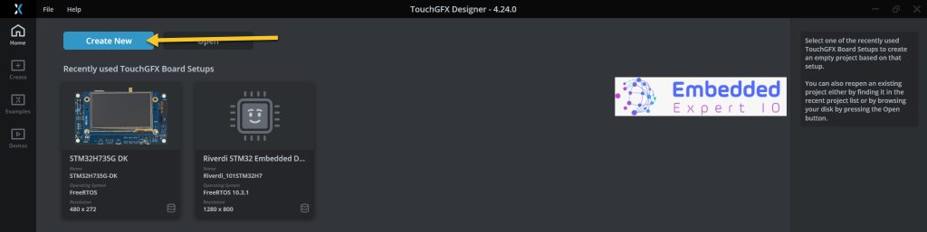
Open TouchGFX designer and create new project as following:
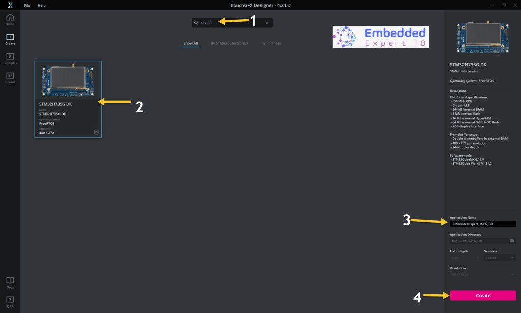
Then select your board, give the project a name and click on create.
After the project has been created, add gauge widget, set minimum to 0, maximum to 1000 and initial value to 0 as following.
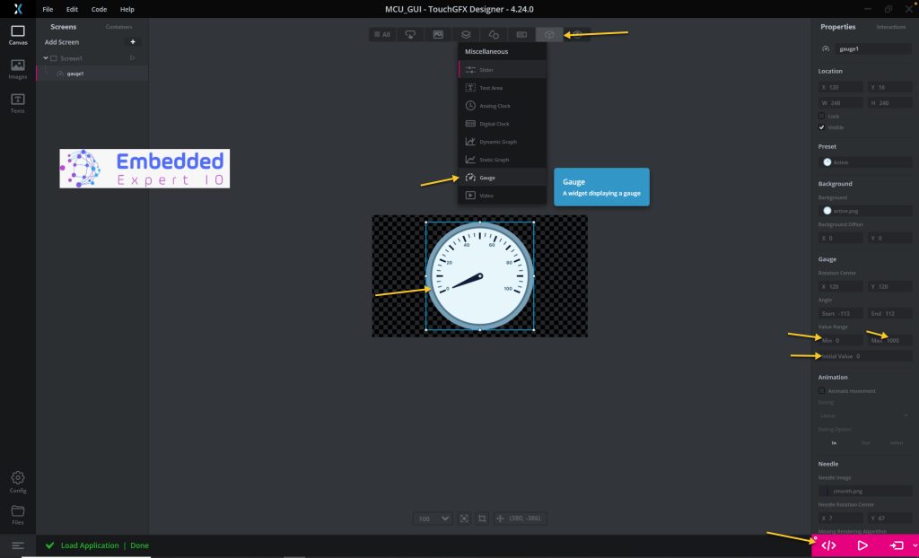
Finally click on generate code or simply, press F3.
That all for the UI.
3. Firmware Development:
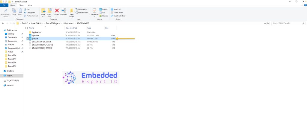
Next, we shall go to the following folder:
ProjectLocation\ProjectName\STM32CubeIDE
Open the .project file and this will open the project within STM32CubeIDE as following:
Next, select the work space and click on Launch as following:
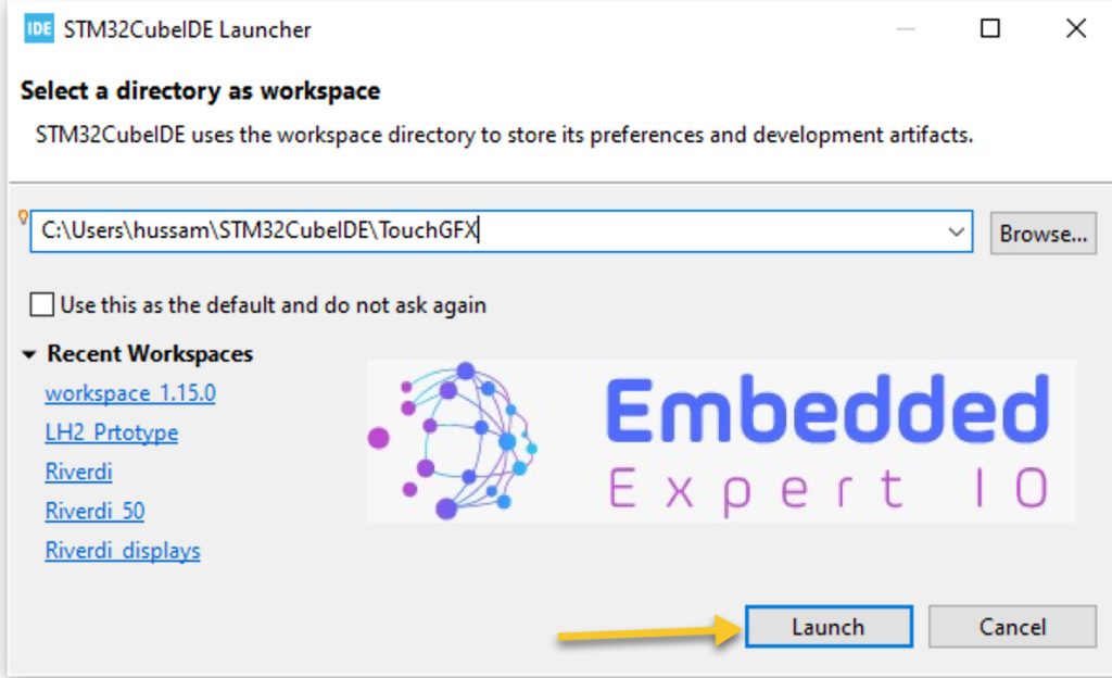
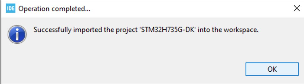
Wait until this window appears:
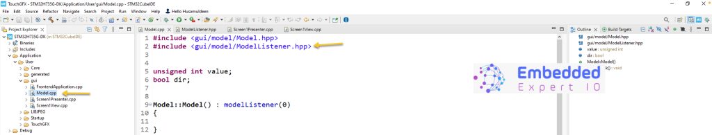
Open Model.cpp from Application, user, GUI, then open modelLister.hpp as following:
Once the hpp header has been opened, in public section of the class, add the following function:
virtual void UpdateGauge(unsigned int value){}Save the project since CubeIDE won’t save it.
Add the same function in the screen1viewer and screen1presenter header file as following:
In Model.cpp source file, declare the following two variables:
unsigned int value;
bool dir;
Value is the counter value.
dir is direction, increment or decrement.
In Model::tick function, add the following:
	if(dir==false)//Increase
	{
		value++;
		if(value==1000)
		{
			value=1000;
			dir=true; //change direction.
		}
	}

	if(dir==true)//Decrease
	{
		value--;
		if(value==0)
		{
			value=0;
			dir=false; //change direction.
		}
	}
	modelListener->UpdateGauge(value);
This function shall be called every frame update (60Hz).
The function shall increment or decrement the value according to the dir variable.
After that, the modelListener shall send the data to update gauge function.
Thats all for the model.cpp.
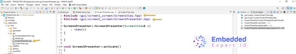
Open Screen1Presenter.cpp source file then add the following function:
void Screen1Presenter::UpdateGauge(unsigned int value)
{
	view.UpdateGauge(value);
}
This function shall be called when the modelListener call the update function, then this function shall call the same function but in the view file.
In Screen1view.cpp source file:
void Screen1View::UpdateGauge(unsigned int value)
{
	gauge1.setValue(value);
	gauge1.invalidate();
}
Here, the view shall update the gauge value.
It is similar to the first part.
Save the project, build it and run it on your STM32H735G-DK board.

4. Results:
Happy coding 😉
Add Comment