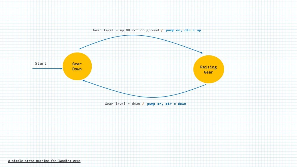
A state machine is defined as an algorithm that can be in one of a small number of states.
A state is a condition that causes a prescribed relationship of inputs to outputs, and of inputs to next states.
One of the advantages of a state machine is that it forces the programmer to think of all the cases and, therefore, to extract all the required information from the user.
Another advantage of using state machines is that the necessary logic can be represented graphically in a state transition diagram. A state transition diagram shows the input/output relationships and the conditions for transitions between states. Also a skeleton of code that implements any state transition diagram can be standardized.
A state machine can be used to build a simple protocol parser.
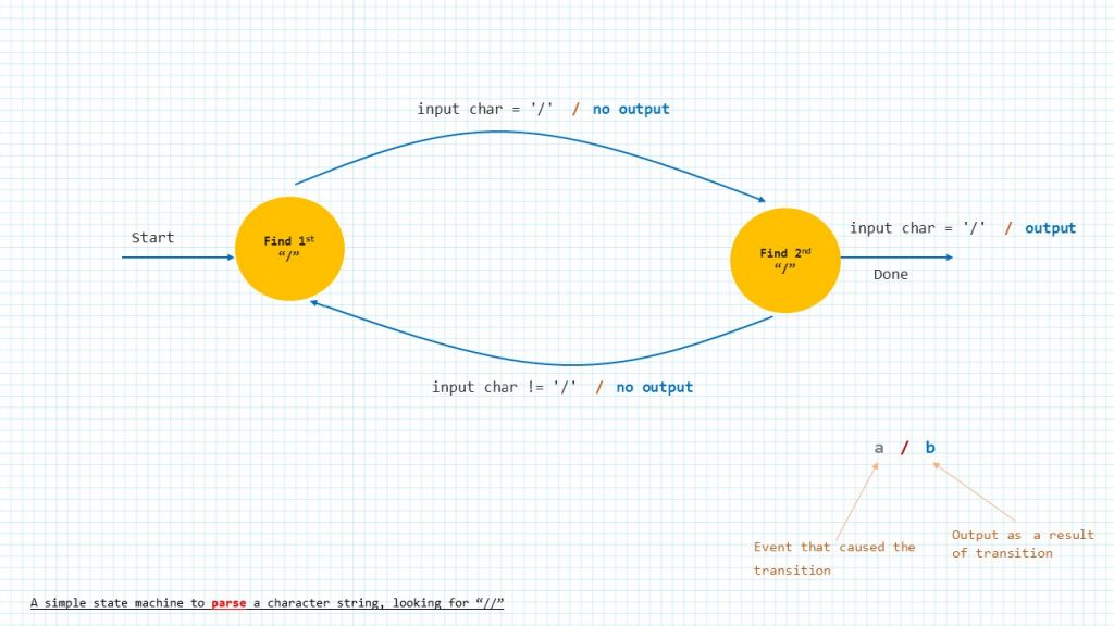
You can think of a parser as something that sort of provides meaning to a piece of information, or you can think of it as an interpreter. Suppose we had to parse a string of text looking for the token “//” in other words double slash. This diagram here shows a state machine to accomplish that.
the first occurrence of a slash produces no output, but causes the machine to advance to the second state. If it encounters a non-slash while in the second state, then it will go back to the first state, because the two slashes must be adjacent. If it finds a second slash, however, then it produces the “we’re done” output.
We can build a state machine for most problems by following a simple 5-step approach. After we have fully understood the problem we want to solve.
We Sketch the state transition diagram, then Code the skeleton of the state machine, without filling in the details of the transition actions, we then, have to make sure the transition works properly, then we flesh out the transition details, once that is done we go ahead and test the state machine. A finite state machine is an algorithm that can be in a finite number of different states.
For example, consider the control algorithm for an ele- vator operating between two floors. The elevator has four possible states: Stopped on floor-1, Stopped on floor-2, Moving up, and Moving down. Inputs include: 1) the buttons that are pushed in the elevator car and on each floor and 2) limit switches indicating that the car has reached either floor. The outputs are the commands to the lift motor, to the elevator doors, and to the indicator displays in the car and on the floors. The outputs and the transition from one state to another depend on the current state and inputs.
Technically, a state machine for which the outputs are functions of both the current state and the inputs is called a Mealy machine. A state machine for which the outputs are functions of only the current state is called a Moore machine. We spend time talking about thee stat machines in their own sections.
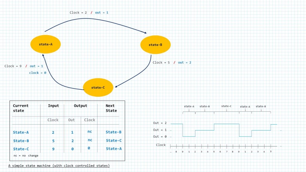
Let’s examine the state transition diagram for a simple example, and see how it might be coded. This system contains three states (A, B, and C). Its only input is the sequential count of a clock (0, 1, 2, . . . ). And, its outputs are a variable called out, and the clock (which the algorithm may reset to 0). The clock increments at a fixed rate. Potential state transitions are evaluated at each clock count.
Lets say the state machine operates as follows: The system stays in state-A until clock=2, then it makes out = 1, and changes to state-B. It stays in state-B until clock=5, then makes out = 2, and changes to state-C. Finally, it stays in state-C until clock=9, then makes out = 0, resets the clock (clock=0), and changes back to state-A. The process repeats indefinitely, producing a periodic output of 9 clock counts. A plot of the output would look like this.
Often the information in the state transition diagram is described the form of a state transition table like this.
Let’s see another example to help us to start getting familiar with the endless use cases of finite state machines.
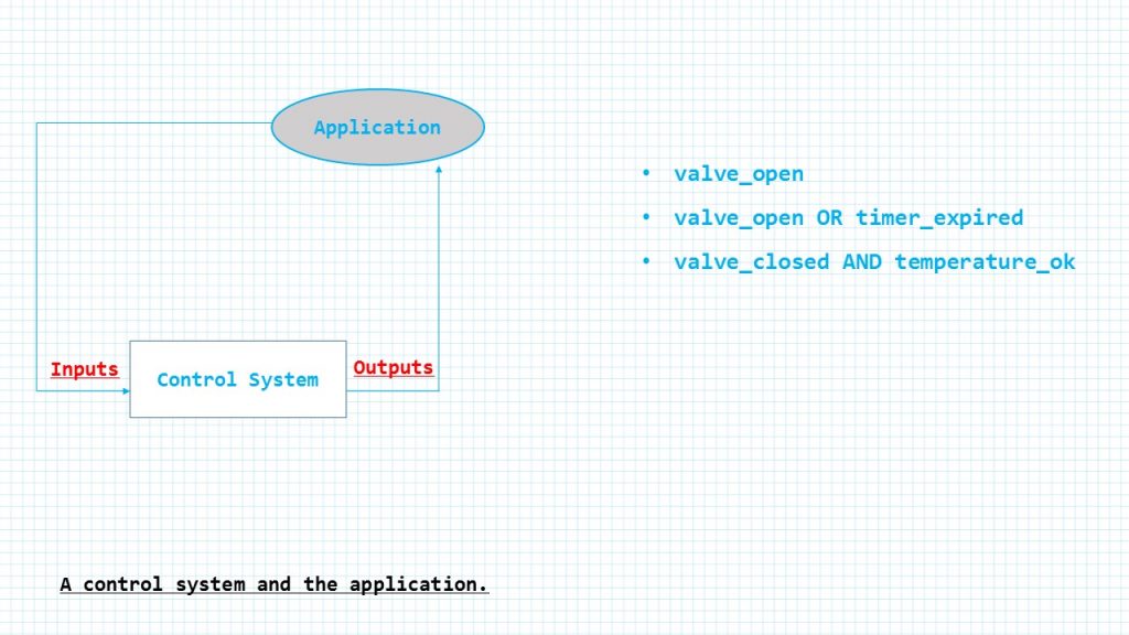
A control system and the application
Lets say we have a control system that controls another system as shown in this illustration.
The Control System receives a number of stimuli (Inputs) from the Application and produces actions (Outputs) to affect the application. The control system realizes the control using simple logical conditions of the form:
If (Input Conditions) Then Outputs
The input conditions are logical expressions formulated according to Boolean algebra. Some examples of Input conditions:
valve_open
valve_open OR timer_expired valve_closed AND temperature_ok
where OR and AND are logical operators. All arguments in these expressions are Boolean values (false, true). In the approach presented in the book we will expand the range of values in input conditions beyond the Boolean values and therefore the NOT operator will not be used.
This simple model is sufficient for rather trivial systems. Any more realistic applications require a much more sophisticated control model. One of the most powerful models is a finite state machine (fsm), which is used to describe behavior: what to do in all imaginable situations.
The finite state machine introduces a concept of a state as information about its past history. All states represent all possible situations in which the state machine may ever be. Hence, it contains a kind of memory: how the state machine can have reached the present situation. As the application runs the state changes from time to time, and outputs may depend on the current state as well as on the inputs.
As the number of distinguishable situations for a given state machine is finite, the number of states is finite. This explains the word “finite” in the name.
A control system determines its outputs depending on its inputs. If the present input values are sufficient to determine the outputs, the system is a combinational system, and does not need the concept of state.
If the control system needs some additional information about the sequence of input changes to determine the outputs, the system is a sequential system.
The logical part of the system responsible for the system behavior is called a state machine. Sometimes combinational systems are treated separately, and sometimes they are considered a kind of degenerated state machine, with only one possible state, to which we could give the name “Always.”
History of input changes required for clear determination of the state machine behavior is stored in an internal variable called State. Both the State transition conditions and the Output conditions are functions of Inputs and a State.
A control system realized as a single state machine is of limited use- fulness. To stay comprehensible a state machine cannot be too complex — the numbers of inputs, outputs, and states have limits. These limits are not fixed constants but result from common sense and depend on the application, the designer, and other factors. For instance, from the documentation point of view a state machine transition diagram should fit on a single A4 or A3 sheet of paper.
State Machine Presentations
A state machine may have different forms that define its ability to describe behavior. The simplest state machine model is a Parser. The function of the Parser is to reflect input changes. The Parser does not produce any specific Outputs its state is the output. A well-known example of a Parser is a state machine that recognizes certain strings. The functioning of a Parser may be shown using a transition matrix or a state transition diagram.
Transition Matrix
A transition matrix is a table where rows represent present states and columns next states. The content of the table are conditions.
The content of the table are conditions that must be fulfilled to make the transition from a present state to the next state true.
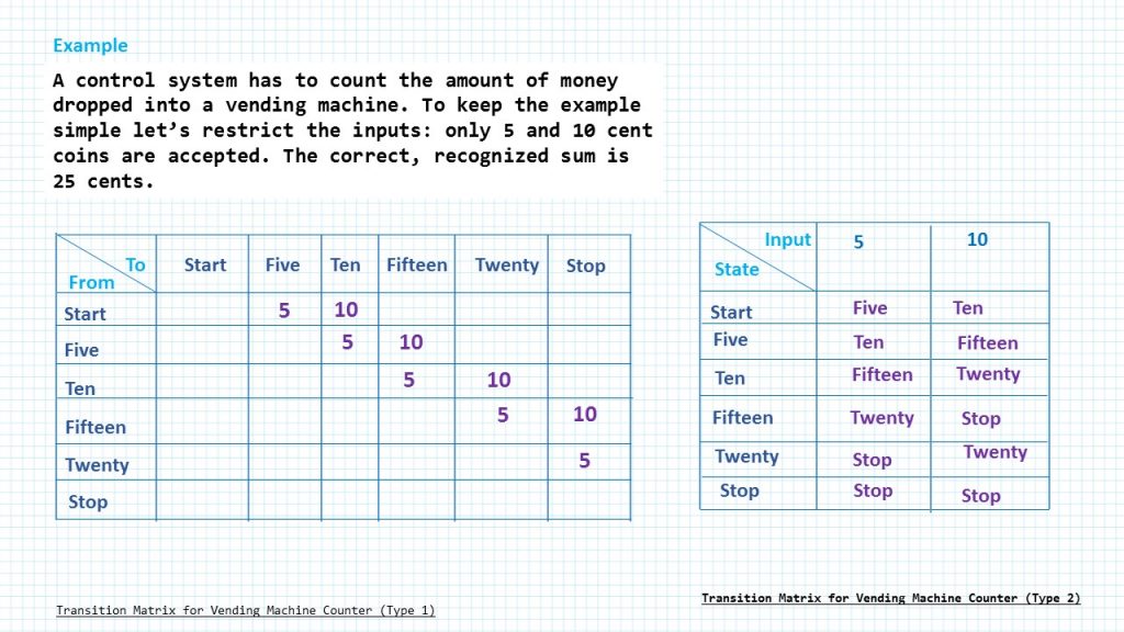
Lets say we have this example. A control system has to count the amount of money dropped into a vending machine. To keep the example simple let’s restrict the inputs: only 5 and 10 cent coins are accepted. The correct, recognized sum is 25 cents.
This is what the transition matrix of this example looks like.
The input conditions are numbers 5 and 10, which correspond to the recognizable coins. A missing condition (-) means an irrelevant or inap- plicable situation (cannot happen). The state Start is the initial start: there are no coins. The state Stop means: there are 25 cents dropped. In all states but Twenty both coins are accepted. In the state Twenty, the 10 cent coin is ignored and rejected, although different strategies could be con- sidered in practice.
A Parser is a state machine that has a beginning state Start and a last state Stop. When a Parser reaches the state Stop its task is successfully terminated and it must be reset to carry out the next recognition process. This sort of machine produces a definite result by means of a single run through a procedure.
In this table the columns represent inputs and the rows — states or vice versa. The content of the table are next states. Given each application we have to decide the form that is more convenient.
#include "uart.h"
#include "stm32f4xx_hal.h"              // Keil::Device:STM32Cube HAL:Common


/*Enumeration (or enum) is a user defined data type in C.
It is mainly used to assign names to integral constants,
the names make a program easy to read and maintain. */


/*Define enumerated type for states*/
enum states{
   STATE_A =0,
	 STATE_B,
	 STATE_C
};

typedef enum states State_Type;

void state_a_function(void);
void state_b_function(void);
void state_c_function(void);
void state_machine_init(void);
void wait(void);

/*Array of pointers to named functions*/
static void (*state_table[])(void)={ state_a_function,
																     state_b_function,
																     state_c_function };
static State_Type current_state;
static int Clock;
static int out;

int main(void) {
    /*Include HAL lib header
		Implement IncTick in Systick Handler*/
    HAL_Init();
    USART2_init();
    state_machine_init();


    while (1) {
		/*Call the current state*/
		state_table[current_state]();
		/*Wait for 10ms*/
		HAL_Delay(1000);
		Clock++;

    }
}


void state_machine_init(void)
{
  current_state = STATE_A;
  Clock = 0;
}

uint32_t sa_prev_time =0;
uint32_t sa_now ;
float sa_tdelta;


void state_a_function(void)
{

  if( Clock == 2 ) { /* Change State? */
     current_state = STATE_B; /* Next State */
		 sa_now = HAL_GetTick();
		 sa_tdelta  = sa_now - sa_prev_time;
		 /*To seconds*/
		 sa_tdelta /=1000;
		 sa_prev_time = sa_now;
 		 printf("This is the ouput of STATE A : %f  seconds ago\n\r", sa_tdelta);
   }
}


uint32_t sb_prev_time =0;
uint32_t sb_now ;
float sb_tdelta;

void state_b_function(void)
{
  if( Clock == 5 ) { /* Change State? */
     current_state = STATE_C; /* Next State */
 		 sb_now = HAL_GetTick();
		 sb_tdelta  = sb_now - sb_prev_time;
		 /*To seconds*/
		 sb_tdelta /=1000;
		 sb_prev_time = sb_now;
 		 printf("This is the ouput of STATE B : %f  seconds ago\n\r", sb_tdelta);
		 printf("\n\r");

   }
}

uint32_t sc_prev_time =0;
uint32_t sc_now ;
float sc_tdelta;

void state_c_function(void)
{
if( Clock == 9 ) { /* Change State? */
    Clock = 0;
    current_state = STATE_A; /* Next State */
		sc_now = HAL_GetTick();
		sc_tdelta  = sc_now - sc_prev_time;
		 /*To seconds*/
		sc_tdelta /=1000;
		sc_prev_time = sc_now;
	 	printf("This is the ouput of STATE  C : %f  seconds ago\n\r", sc_tdelta);

  }
}

void SysTick_Handler(void){
   HAL_IncTick();
}
Add Comment